Snubber circuits protect components from voltage spikes by dissipating energy through resistors and capacitors, while clamp circuits limit voltage to a preset level using diodes or zener diodes to prevent damage. Explore the article to understand how each circuit functions and which best suits Your electronic design needs.
Table of Comparison
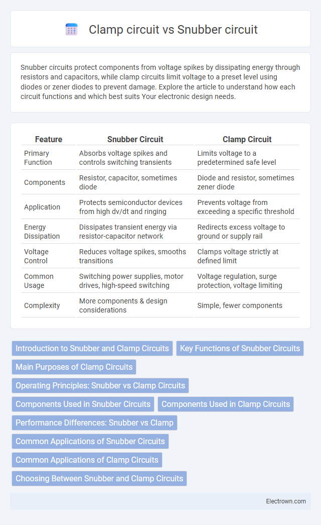
| Feature | Snubber Circuit | Clamp Circuit |
|---|---|---|
| Primary Function | Absorbs voltage spikes and controls switching transients | Limits voltage to a predetermined safe level |
| Components | Resistor, capacitor, sometimes diode | Diode and resistor, sometimes zener diode |
| Application | Protects semiconductor devices from high dv/dt and ringing | Prevents voltage from exceeding a specific threshold |
| Energy Dissipation | Dissipates transient energy via resistor-capacitor network | Redirects excess voltage to ground or supply rail |
| Voltage Control | Reduces voltage spikes, smooths transitions | Clamps voltage strictly at defined limit |
| Common Usage | Switching power supplies, motor drives, high-speed switching | Voltage regulation, surge protection, voltage limiting |
| Complexity | More components & design considerations | Simple, fewer components |
Introduction to Snubber and Clamp Circuits
Snubber circuits protect semiconductor devices by controlling voltage spikes and transient voltages through RC or RCD networks, enhancing reliability in power electronics. Clamp circuits limit voltage excursions by diverting excess voltage to a reference voltage level, often using diodes or zener diodes to safeguard components. Both circuits mitigate voltage stress but differ in operation, with snubbers dissipating energy and clamps redirecting it.
Key Functions of Snubber Circuits
Snubber circuits primarily protect power electronic devices by absorbing voltage spikes and suppressing oscillations during switching operations in circuits such as inductive loads and transformers. They enhance the reliability of MOSFETs and IGBTs by limiting voltage transients and reducing electromagnetic interference (EMI). Effective snubber circuits improve circuit longevity, minimize switching losses, and ensure stable operation in power converters and motor drives.
Main Purposes of Clamp Circuits
Clamp circuits primarily protect electronic components by limiting voltage spikes to a specific level, ensuring voltage remains within safe bounds. They stabilize signal waveforms by shifting voltage levels without altering the shape, which is crucial in digital and analog circuits. Your system's reliability improves as clamp circuits prevent damage from transient overvoltages and maintain signal integrity.
Operating Principles: Snubber vs Clamp Circuits
Snubber circuits operate by absorbing voltage spikes and controlling transient energy through resistors, capacitors, or RC networks to protect switching devices. Clamp circuits function by limiting voltage levels to a predetermined threshold using diodes or Zener diodes, ensuring voltage does not exceed safe limits. While snubbers dissipate energy to smooth transitions, clamps redirect or restrict voltage to prevent overvoltage conditions.
Components Used in Snubber Circuits
Snubber circuits typically use components such as resistors, capacitors, and sometimes diodes to absorb voltage spikes and limit di/dt and dv/dt in power electronics, protecting switching devices from transient stress. These components form RC, RCD, or diode-capacitor snubbers, each tailored to specific transient suppression requirements. Your choice of snubber components directly impacts the effectiveness of transient energy dissipation and overall circuit reliability.
Components Used in Clamp Circuits
Clamp circuits primarily use diodes, resistors, and capacitors to stabilize voltage and limit transient spikes. These components work together by directing excess voltage away from sensitive parts, with diodes providing directional control and capacitors absorbing and releasing energy to smooth fluctuations. Resistors in clamp circuits help dissipate energy and fine-tune the voltage limiting function for circuit protection.
Performance Differences: Snubber vs Clamp
Snubber circuits primarily protect semiconductor devices by absorbing voltage spikes and controlling di/dt, improving switching performance and reducing electromagnetic interference. Clamp circuits limit voltage overshoot by redirecting excess energy to a safe path, offering faster response but less control over voltage and current waveforms. Snubbers provide more precise transient suppression at the cost of complexity, whereas clamps offer simpler, cost-effective protection with faster activation times.
Common Applications of Snubber Circuits
Snubber circuits are commonly used in power electronics to protect switching devices such as transistors and MOSFETs from voltage spikes and to reduce electromagnetic interference (EMI) during switching transitions. They are frequently applied in DC-DC converters, motor drives, and inverter circuits to enhance device reliability and extend component lifespan. Unlike clamp circuits that primarily limit voltage to a fixed level, snubber circuits absorb and dissipate transient energy, making them essential for managing inductive load switching effects.
Common Applications of Clamp Circuits
Clamp circuits are commonly used in signal processing to restore DC levels by shifting waveform voltages, making them essential in waveform shaping and pulse restoration. They find frequent applications in television receivers for picture signal stabilization, in analog communication systems to align voltage levels, and in protecting electronic components from voltage spikes by limiting voltage excursions. Clamp circuits also play a crucial role in digital circuits for level shifting and ensuring signal integrity in waveforms with varying baselines.
Choosing Between Snubber and Clamp Circuits
Choosing between snubber and clamp circuits depends on the specific application requirements such as voltage spike suppression and energy dissipation. Snubber circuits effectively control transient voltages and damp oscillations, making them ideal for protecting switching devices in power electronics. Clamp circuits provide a fixed voltage limit to prevent overvoltage conditions, offering a simpler solution when precise voltage clamping is needed for your system's stability.
Snubber circuit vs clamp circuit Infographic