A ground loop occurs when there are multiple grounding paths creating unwanted current flow, which can introduce noise into audio and electronic systems, while a floating ground is an isolated grounding point not connected to earth, reducing interference but potentially causing safety issues. Understanding the differences between ground loop and floating ground can help you optimize your system's performance and safety; read on to explore their applications and troubleshooting tips.
Table of Comparison
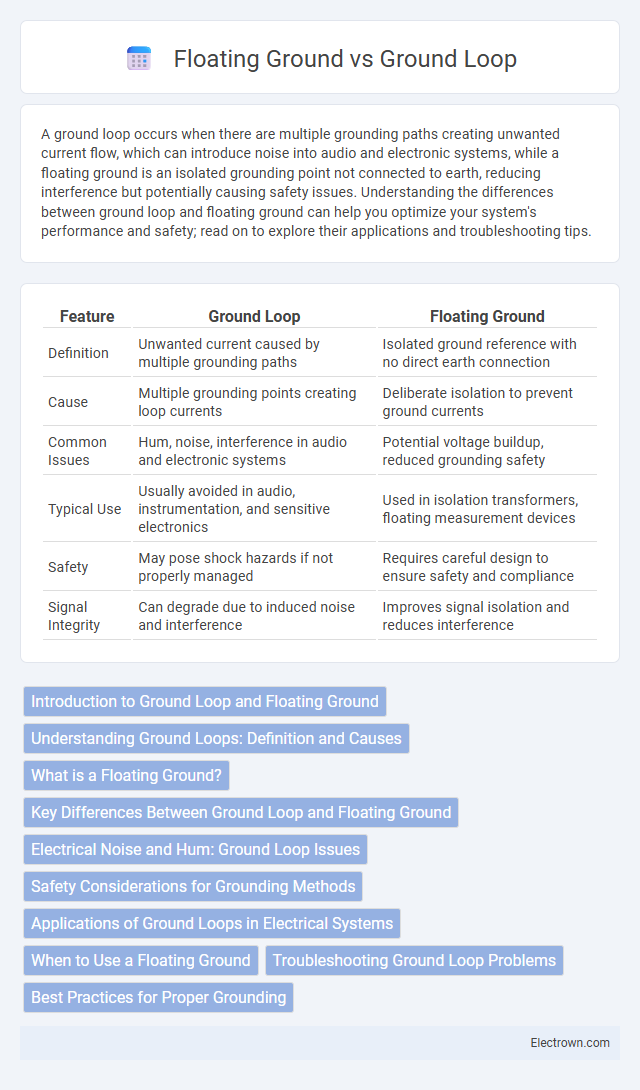
| Feature | Ground Loop | Floating Ground |
|---|---|---|
| Definition | Unwanted current caused by multiple grounding paths | Isolated ground reference with no direct earth connection |
| Cause | Multiple grounding points creating loop currents | Deliberate isolation to prevent ground currents |
| Common Issues | Hum, noise, interference in audio and electronic systems | Potential voltage buildup, reduced grounding safety |
| Typical Use | Usually avoided in audio, instrumentation, and sensitive electronics | Used in isolation transformers, floating measurement devices |
| Safety | May pose shock hazards if not properly managed | Requires careful design to ensure safety and compliance |
| Signal Integrity | Can degrade due to induced noise and interference | Improves signal isolation and reduces interference |
Introduction to Ground Loop and Floating Ground
Ground loops occur when multiple grounding paths create unintended current flow, leading to noise and interference in electronic systems. Floating grounds refer to circuits or devices that have no direct connection to the earth ground, allowing for isolation from ground potential but increasing susceptibility to voltage differences. Understanding the distinction between ground loop and floating ground is critical for designing noise-free and stable electrical systems.
Understanding Ground Loops: Definition and Causes
Ground loops occur when multiple grounding paths create a closed electrical circuit, causing unwanted current flow that leads to noise and interference in audio, video, or sensitive electronic equipment. Understanding these loops requires recognizing that differences in ground potential between interconnected devices are the primary cause, often resulting from improper wiring or grounding practices. Identifying and correcting ground loops helps ensure the integrity of your signal and prevents electromagnetic disturbances affecting system performance.
What is a Floating Ground?
A floating ground refers to a reference point in an electrical circuit that is not connected to the earth or chassis ground, isolating it from ground potential to prevent unwanted current paths and interference. It is commonly used in sensitive measurement equipment and isolation amplifiers to reduce noise and ground loop issues. Unlike a grounded system, a floating ground can help eliminate ground loop currents, but requires careful insulation and design to avoid voltage buildup and ensure safety.
Key Differences Between Ground Loop and Floating Ground
Ground loop occurs when multiple grounding paths create unwanted current flow, causing noise and interference in electrical systems, while a floating ground is an isolated reference point not connected to the earth or common ground, preventing ground loop issues. Ground loop typically results in voltage differences between grounds, leading to hum and signal distortion, whereas floating grounds maintain signal integrity by avoiding potential ground-induced noise. Devices with floating grounds are essential in sensitive audio and measurement equipment to ensure accurate, noise-free operation compared to systems affected by ground loops.
Electrical Noise and Hum: Ground Loop Issues
Ground loops occur when multiple grounding paths create unintended current flow, causing electrical noise and hum in audio and video systems. Floating grounds lack a direct connection to the earth reference, which can reduce the risk of ground loop interference but may also increase susceptibility to static discharge and signal instability. Proper grounding design minimizes noise by ensuring a single, low-impedance ground path that prevents loop currents and maintains signal integrity.
Safety Considerations for Grounding Methods
Ground loops can create dangerous voltage differences that pose shock hazards and interfere with proper equipment operation, making safety a key concern in grounding methods. Floating grounds isolate circuits to prevent these hazardous currents but require careful design to avoid unintended voltage buildup. Your choice of grounding method must prioritize preventing electrical shock and ensuring system stability to maintain a safe operating environment.
Applications of Ground Loops in Electrical Systems
Ground loops commonly occur in electrical systems where multiple grounding points create unwanted current paths, often causing noise in audio and video equipment. They are intentionally utilized in protective earth configurations to ensure safety by providing a low-resistance path to dissipate fault currents. Ground loops also facilitate signal reference stability in complex instrumentation setups, enhancing measurement accuracy by minimizing electromagnetic interference.
When to Use a Floating Ground
A floating ground is ideal when isolating sensitive audio or measurement equipment from earth ground to reduce noise and ground loop interference. You should use a floating ground in situations where multiple grounded devices cause hum or interference, such as in audio mixers or medical instruments. This approach prevents current flow through grounding paths, preserving signal integrity in your system.
Troubleshooting Ground Loop Problems
Troubleshooting ground loop problems requires identifying and isolating the specific ground paths causing unwanted current flow and noise interference in audio or electrical systems. Using differential measurement tools such as multimeters or oscilloscopes helps detect voltage discrepancies between grounds, revealing potential loop sources. Implementing solutions like isolating grounds with ground loop isolators, reconfiguring wiring, or using floating grounds can effectively eliminate hum, buzz, or signal degradation.
Best Practices for Proper Grounding
Proper grounding techniques differentiate ground loops from floating grounds to prevent noise interference and ensure safety in electrical systems. Best practices include using a single-point grounding system to avoid multiple ground paths that create ground loops and ensuring floating grounds are connected correctly to the main reference ground to maintain signal integrity. Implementing shielded cables and isolating sensitive equipment further minimizes electromagnetic interference and enhances system performance.
Ground loop vs floating ground Infographic