Common Source amplifiers provide high voltage gain and moderate input impedance, making them ideal for voltage amplification in many analog circuits. Understanding the differences between Common Source and Common Gate configurations can enhance your circuit design skills; continue reading to explore their specific applications and performance characteristics.
Table of Comparison
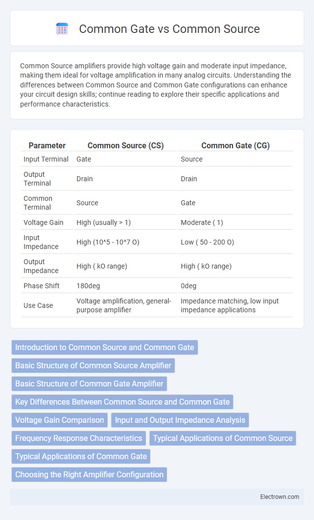
| Parameter | Common Source (CS) | Common Gate (CG) |
|---|---|---|
| Input Terminal | Gate | Source |
| Output Terminal | Drain | Drain |
| Common Terminal | Source | Gate |
| Voltage Gain | High (usually > 1) | Moderate ( 1) |
| Input Impedance | High (10^5 - 10^7 O) | Low ( 50 - 200 O) |
| Output Impedance | High ( kO range) | High ( kO range) |
| Phase Shift | 180deg | 0deg |
| Use Case | Voltage amplification, general-purpose amplifier | Impedance matching, low input impedance applications |
Introduction to Common Source and Common Gate
The common source amplifier configuration features the input signal applied to the gate while the output is taken from the drain, offering high voltage gain and moderate input impedance. The common gate amplifier applies the input signal to the source terminal with the gate held at a fixed voltage, providing low input impedance and high-frequency performance. These fundamental differences make common source ideal for voltage amplification and common gate suitable for impedance matching and wideband applications.
Basic Structure of Common Source Amplifier
The basic structure of a common source amplifier consists of a single MOSFET with the source terminal connected to ground, the gate terminal serving as the input, and the drain terminal connected to a load resistor or active load. This configuration provides high voltage gain due to the transistor's transconductance and the load impedance at the drain. The input signal at the gate modulates the channel resistance, producing an amplified output voltage at the drain relative to the source node.
Basic Structure of Common Gate Amplifier
The basic structure of a common gate amplifier consists of a metal-oxide-semiconductor field-effect transistor (MOSFET) where the gate terminal is connected to a fixed voltage, often ground or a bias voltage, serving as the reference point. The input signal is applied to the source terminal, while the output is taken from the drain terminal, allowing the device to function as a voltage amplifier with low input impedance. Understanding this configuration helps you optimize circuit design, especially in high-frequency applications requiring stable gain and bandwidth.
Key Differences Between Common Source and Common Gate
The key differences between common source and common gate amplifier configurations lie in their input and output connections, voltage gain, and phase shift characteristics. Common source amplifiers provide high voltage gain with an output signal phase inverted by 180 degrees relative to the input, while common gate amplifiers offer low input impedance, unity or slightly less voltage gain, and no phase inversion. Additionally, common gate stages are preferred for high-frequency applications due to their wider bandwidth, whereas common source stages excel in voltage amplification at lower frequencies.
Voltage Gain Comparison
Common Source amplifiers typically provide higher voltage gain compared to Common Gate stages due to their higher intrinsic gain and greater transconductance efficiency. The voltage gain of a Common Source configuration can often reach values of 20 to 100, whereas Common Gate amplifiers usually exhibit lower gains, generally below 10, because of reduced input impedance and feedback effects. Design choices often favor Common Source for applications requiring substantial voltage amplification while Common Gate suits high-frequency or low input impedance scenarios.
Input and Output Impedance Analysis
The common source amplifier features high input impedance, typically in the megaohm range due to the gate terminal's insulated nature, making it highly suitable for voltage amplification with minimal loading on the input signal. Its output impedance is moderate to high, influenced by the transistor's drain resistance and load, which affects voltage gain and frequency response. In contrast, the common gate amplifier exhibits low input impedance, often below a few hundred ohms, because the source terminal provides a direct path to the input signal, making it ideal for current buffering and high-frequency applications while maintaining a relatively low output impedance similar to the common source configuration.
Frequency Response Characteristics
Common Source amplifiers typically exhibit high voltage gain with a moderate bandwidth, making them effective for mid-frequency applications due to their dominant low-frequency pole and gain-bandwidth trade-off. Common Gate configurations offer superior high-frequency response and wider bandwidth, as their input impedance minimizes Miller effect, leading to better performance in radio frequency (RF) circuits. Frequency response in Common Gate stages emphasizes flat gain over a broad spectrum, while Common Source amplifiers often require compensation techniques to maintain stability at higher frequencies.
Typical Applications of Common Source
Common Source amplifiers are widely used in audio frequency amplifiers, voltage amplifiers, and signal processing circuits due to their high voltage gain and moderate input impedance. They are essential in analog circuit design for applications such as active filters, oscillators, and buffer stages in sensors and communication devices. Common Source stages excel at converting small input voltage signals into larger output voltage swings, making them ideal for initial amplification in various electronic systems.
Typical Applications of Common Gate
Common Gate amplifiers are typically used in high-frequency applications due to their low input impedance, making them ideal for RF amplifiers and impedance matching circuits. They excel in wideband amplifiers and current buffering where voltage gain is important without phase inversion. Common Gate configurations are also favored in amplifier stages requiring stable gain and good high-frequency response.
Choosing the Right Amplifier Configuration
When choosing the right amplifier configuration, the common source amplifier offers high voltage gain and moderate input impedance, making it suitable for voltage amplification in general-purpose applications. The common gate amplifier provides low input impedance and high output impedance, ideal for high-frequency scenarios and impedance matching in RF circuits. Understanding the trade-offs in gain, input/output impedance, and bandwidth ensures optimal performance tailored to specific signal amplification requirements.
Common Source vs Common Gate Infographic