Active high signals trigger a circuit or device when the voltage level is high, while active low signals activate when the voltage level is low. Understanding this difference is crucial for designing and troubleshooting digital systems; explore the rest of the article to learn how it impacts your electronics projects.
Table of Comparison
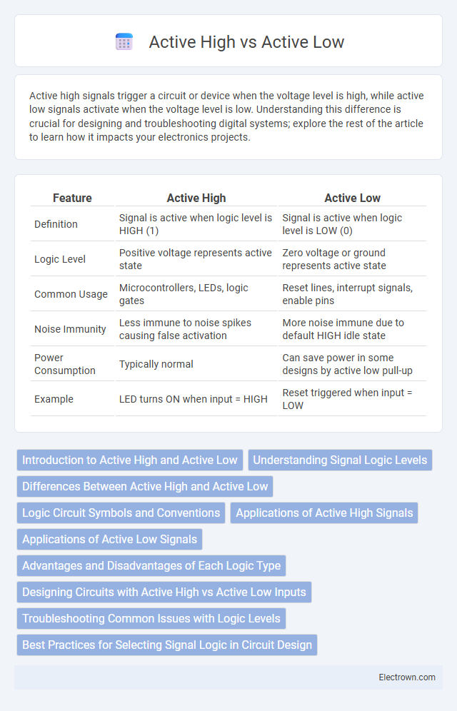
| Feature | Active High | Active Low |
|---|---|---|
| Definition | Signal is active when logic level is HIGH (1) | Signal is active when logic level is LOW (0) |
| Logic Level | Positive voltage represents active state | Zero voltage or ground represents active state |
| Common Usage | Microcontrollers, LEDs, logic gates | Reset lines, interrupt signals, enable pins |
| Noise Immunity | Less immune to noise spikes causing false activation | More noise immune due to default HIGH idle state |
| Power Consumption | Typically normal | Can save power in some designs by active low pull-up |
| Example | LED turns ON when input = HIGH | Reset triggered when input = LOW |
Introduction to Active High and Active Low
Active high and active low configurations define how digital signals are interpreted in electronic circuits, where active high means a logic signal is considered "ON" or true at a high voltage level, typically close to the supply voltage. In contrast, active low indicates a signal is "ON" or true when the voltage level is low, near ground potential. Understanding these concepts is crucial for designing and troubleshooting digital systems, as they determine how inputs, outputs, and control signals behave under various conditions.
Understanding Signal Logic Levels
Active high signals use a logic level '1' (usually +5V or +3.3V) to represent an active or asserted state, while active low signals employ a logic level '0' (ground or 0V) for activation. Understanding these signal logic levels is crucial for designing digital circuits and interfacing components correctly, ensuring reliable signal interpretation and operation. Proper identification of active high and active low configurations helps prevent errors in logic gates, microcontroller inputs, and communication protocols.
Differences Between Active High and Active Low
Active high and active low signals differ primarily in their voltage level that triggers a device or circuit action: active high activates when the signal is at a high voltage level, whereas active low activates when the signal is at a low voltage level. In digital electronics, active high logic uses a positive voltage (e.g., +5V) to represent a logical '1' or true state, while active low logic uses ground or zero volts to represent this state, often denoted by a bar or an overline on the signal name (e.g., \(\overline{RESET}\)). Understanding these differences is crucial for designing and troubleshooting circuits, ensuring correct interpretation of control signals and preventing unintended device behavior.
Logic Circuit Symbols and Conventions
Active high and active low logic circuit symbols differ in how they represent signal activation: active high inputs or outputs are typically shown without bubbles on logic gates, indicating a logic '1' or high voltage triggers the function; active low signals include a small circle (bubble) at the input or output, denoting activation by a logic '0' or low voltage. These conventions help you quickly identify the signal polarity and understand circuit behavior when reading schematics. Recognizing these symbols ensures accurate interpretation and proper design of digital circuits using standard logic gates.
Applications of Active High Signals
Active high signals are predominantly used in digital electronics for straightforward control operations because a high voltage level represents an "on" or "true" state, simplifying logic design and troubleshooting. Common applications include enabling microcontroller inputs, activating LEDs, and triggering relays where a logical high voltage signifies device activation. These signals are essential in systems requiring clear, direct indication of states for efficient signal processing and control.
Applications of Active Low Signals
Active low signals are widely used in digital electronics to simplify circuit design and improve noise immunity, commonly found in microcontroller reset lines and memory chip enable inputs. These signals ensure that devices activate only when the line is driven to a low voltage level, reducing the risk of false triggering due to electrical noise. Industrial control systems and communication protocols also utilize active low signals for reliable device activation and signal integrity.
Advantages and Disadvantages of Each Logic Type
Active high logic signals are advantageous because they are often easier to design and troubleshoot due to their intuitive "high" or logic '1' state representing active conditions, but they can be more susceptible to noise interference in noisy environments. Active low logic signals provide improved noise immunity because the active state is represented by a '0' or low voltage level, reducing false triggering, though this can complicate circuit design and interpretation for engineers. Designers must consider these trade-offs to decide between simpler implementation with active high versus enhanced noise resistance with active low logic.
Designing Circuits with Active High vs Active Low Inputs
Designing circuits with active high inputs means that the device or signal is activated when the input is at a high voltage level, typically representing a logical "1." Active low inputs require the signal to be at a low voltage level, or logical "0," to trigger the function, often indicated by a bar or a slash in schematics (e.g., \overline{CLR}). Understanding the distinction helps engineers optimize noise immunity, power consumption, and interface compatibility when selecting microcontrollers, logic gates, or control signals in digital circuit design.
Troubleshooting Common Issues with Logic Levels
Troubleshooting common issues with logic levels requires understanding the distinction between active high and active low signals to correctly interpret circuit behavior. Misinterpreting an active low signal as active high can cause unintended device activation or failure to respond, leading to diagnostic confusion. Ensuring your equipment and test probes align with the expected logic levels helps prevent misreadings and facilitates accurate problem resolution.
Best Practices for Selecting Signal Logic in Circuit Design
Choosing between active high and active low signals in circuit design depends on factors like noise immunity, power consumption, and system compatibility. Active low signals often provide better noise tolerance and are commonly used in open-collector or open-drain configurations due to their fail-safe nature. Best practices include aligning signal logic with the device's input characteristics and ensuring consistent logic conventions across interconnected components to prevent design errors.
Active high vs active low Infographic