Setup time and hold time are critical parameters in digital circuits that ensure data stability during clock transitions; setup time is the minimum period data must be stable before the clock edge, while hold time is the minimum period data must remain stable after the clock edge. Understanding these timing constraints helps you design reliable systems and avoid metastability issues--read on to explore detailed explanations and practical examples.
Table of Comparison
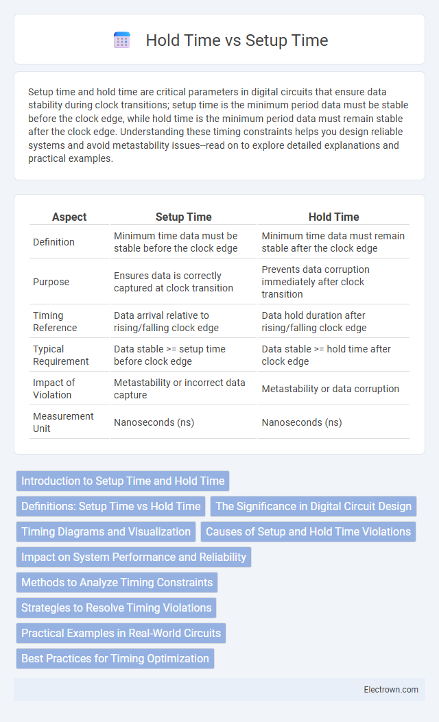
| Aspect | Setup Time | Hold Time |
|---|---|---|
| Definition | Minimum time data must be stable before the clock edge | Minimum time data must remain stable after the clock edge |
| Purpose | Ensures data is correctly captured at clock transition | Prevents data corruption immediately after clock transition |
| Timing Reference | Data arrival relative to rising/falling clock edge | Data hold duration after rising/falling clock edge |
| Typical Requirement | Data stable >= setup time before clock edge | Data stable >= hold time after clock edge |
| Impact of Violation | Metastability or incorrect data capture | Metastability or data corruption |
| Measurement Unit | Nanoseconds (ns) | Nanoseconds (ns) |
Introduction to Setup Time and Hold Time
Setup time refers to the minimum period before the clock edge during which data must remain stable to ensure correct sampling, while hold time is the minimum duration after the clock edge that data must be maintained stable to avoid timing errors. Both parameters are critical in synchronous digital circuits to guarantee data integrity and proper flip-flop operation. Violating setup or hold time constraints can cause metastability, resulting in unpredictable circuit behavior and data corruption.
Definitions: Setup Time vs Hold Time
Setup time refers to the minimum period before the clock edge during which data must remain stable to ensure correct sampling, while hold time is the minimum duration after the clock edge that data must be held stable to avoid metastability. These timing parameters are critical in synchronous digital circuits to guarantee data integrity and proper operation of flip-flops or latches. Understanding your system's setup and hold times helps optimize timing constraints and improves reliability in high-speed designs.
The Significance in Digital Circuit Design
Setup time and hold time are critical parameters in digital circuit design that ensure data stability and proper synchronization between flip-flops and registers. Violating setup time can cause data to be latched incorrectly, leading to timing errors, while failing to meet hold time requirements may result in metastability and unpredictable circuit behavior. Accurate management of these timing constraints is essential for reliable high-speed digital system performance and signal integrity.
Timing Diagrams and Visualization
Timing diagrams visualize Setup Time and Hold Time by clearly showing when data must be stable before and after the clock edge to ensure proper latch operation. Setup Time is represented as the interval before the clock transition during which input data must be steady, while Hold Time indicates the period after the clock edge that data must remain unchanged. Your ability to interpret these diagrams helps prevent timing violations, ensuring reliable circuit performance.
Causes of Setup and Hold Time Violations
Setup time violations occur when data does not arrive early enough before the clock edge, often caused by slow data paths or clock skew delaying data arrival. Hold time violations arise when data changes too soon after the clock edge, typically due to fast data paths, insufficient delay buffers, or clock skew causing premature data transitions. Both violations compromise reliable data capture in flip-flops and can lead to metastability or functional errors in synchronous circuits.
Impact on System Performance and Reliability
Setup time and hold time directly affect system clock frequency and timing margins, influencing overall system performance. Violations of setup time can cause data to be latched incorrectly, resulting in metastability and reliability issues. Ensuring proper timing constraints enhances signal integrity, reduces errors, and improves the robustness of synchronous digital circuits.
Methods to Analyze Timing Constraints
Analyzing timing constraints like setup time and hold time involves static timing analysis (STA) tools that evaluate signal arrival times and clock timings to ensure data stability and prevent timing violations. Techniques such as timing waveform simulation and timing slack measurement help identify critical paths and potential setup or hold violations. Your design's reliability depends on accurately balancing these timing requirements to maintain data integrity across all operating conditions.
Strategies to Resolve Timing Violations
To resolve timing violations related to setup time, increasing the clock period or optimizing combinational logic paths can effectively ensure data stabilizes before the clock edge. Adjusting hold time violations often involves adding delay elements or skewing the clock to prevent data from changing too soon after the clock edge. Your timing analysis tools can help identify the exact sources of setup and hold violations, guiding targeted interventions to maintain signal integrity and reliable circuit performance.
Practical Examples in Real-World Circuits
Setup time and hold time are critical parameters in the design of flip-flops and sequential circuits, ensuring data is correctly latched without errors. In real-world circuits like microprocessors and memory devices, violating setup time can cause metastability, leading to unpredictable outputs, while hold time violations may result in data corruption. Understanding and optimizing these timings in your design prevents timing hazards and ensures reliable operation at high clock speeds.
Best Practices for Timing Optimization
Setup time and hold time are critical parameters in digital circuit design that ensure data stability before and after the clock edge, respectively. To optimize timing, you should minimize setup time by reducing combinational path delays and enhance hold time by adding delay buffers or balancing path lengths to prevent data races. Implementing clock skew management and thorough timing analysis helps maintain reliable data capture within both setup and hold time constraints, improving overall circuit performance.
Setup Time vs Hold Time Infographic