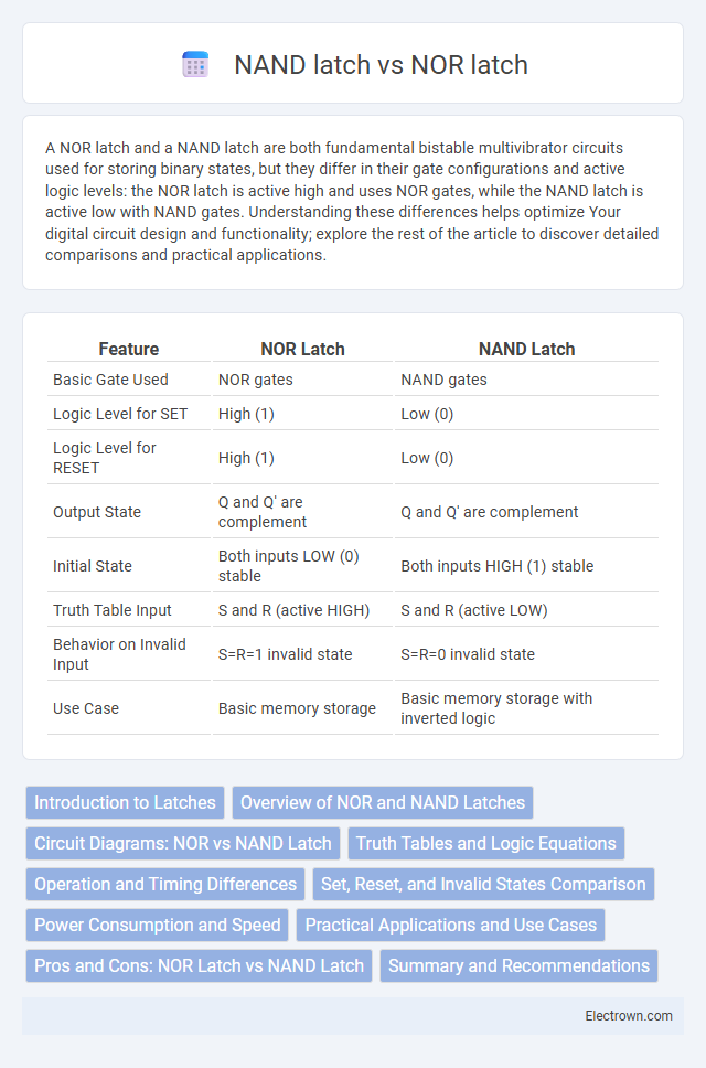
A NOR latch and a NAND latch are both fundamental bistable multivibrator circuits used for storing binary states, but they differ in their gate configurations and active logic levels: the NOR latch is active high and uses NOR gates, while the NAND latch is active low with NAND gates. Understanding these differences helps optimize Your digital circuit design and functionality; explore the rest of the article to discover detailed comparisons and practical applications.
Table of Comparison
| Feature | NOR Latch | NAND Latch |
|---|---|---|
| Basic Gate Used | NOR gates | NAND gates |
| Logic Level for SET | High (1) | Low (0) |
| Logic Level for RESET | High (1) | Low (0) |
| Output State | Q and Q' are complement | Q and Q' are complement |
| Initial State | Both inputs LOW (0) stable | Both inputs HIGH (1) stable |
| Truth Table Input | S and R (active HIGH) | S and R (active LOW) |
| Behavior on Invalid Input | S=R=1 invalid state | S=R=0 invalid state |
| Use Case | Basic memory storage | Basic memory storage with inverted logic |
Introduction to Latches
NOR latch and NAND latch are fundamental types of bistable multivibrators used to store binary information in digital circuits. The NOR latch is active-high, meaning it sets or resets on high input signals, while the NAND latch operates on active-low inputs, triggering state changes when inputs go low. Your choice between these latches depends on the specific logic level requirements and design constraints of your digital system.
Overview of NOR and NAND Latches
NOR latch and NAND latch are fundamental bistable multivibrators used for storing one bit of data in digital circuits. The NOR latch uses cross-coupled NOR gates, producing an active-high output, while the NAND latch employs cross-coupled NAND gates, resulting in an active-low output. Both latches operate based on feedback loops that maintain their state until an input change triggers a state transition, making them essential components in memory and flip-flop designs.
Circuit Diagrams: NOR vs NAND Latch
The NOR latch circuit diagram features two cross-coupled NOR gates with inputs labeled S (Set) and R (Reset) that control the output states Q and Q (Q bar), creating a basic bistable flip-flop. In contrast, the NAND latch circuit diagram also uses two cross-coupled NAND gates with inverted inputs, where S and R are active-low signals, meaning the latch is set or reset when these inputs are low. Your choice between NOR and NAND latches depends on input logic levels and signal polarity requirements in digital circuits.
Truth Tables and Logic Equations
A NOR latch uses NOR gates with the truth table showing that when both inputs are low, the latch maintains its state, while setting and resetting occur with S=1, R=0 and S=0, R=1, respectively, described by Q = !(S + !Q) and Q = !(R + Q). A NAND latch utilizes NAND gates, featuring active-low inputs where the latch holds state when both inputs are high, with setting and resetting triggered by S=0, R=1 and S=1, R=0 respectively, governed by Q = !(S * Q) and Q = !(R * Q). The key difference in truth tables lies in the active levels of inputs and the complementary logic equations that define the output states for each latch type.
Operation and Timing Differences
NOR latch operates with active-high inputs, setting and resetting the output when the inputs transition from low to high, making it level-sensitive with a direct feedback loop for faster response. NAND latch uses active-low inputs, causing the latch to respond when inputs transition from high to low, often resulting in inverted logic behavior and slightly longer propagation delays due to different transistor arrangements. Timing differences arise as NOR latches generally exhibit quicker switching times for setting/resetting states, while NAND latches may have higher noise margins but slower response due to input polarity and internal gate delays.
Set, Reset, and Invalid States Comparison
The NOR latch sets the output to high when the Set input is activated and resets it to low when the Reset input is triggered, with an invalid state occurring when both Set and Reset are high simultaneously. The NAND latch operates inversely, setting the output low when the Set input is low and resetting it high when the Reset input is low, encountering an invalid state when both inputs are low at the same time. Understanding these differences is crucial for designing stable memory elements in digital circuits.
Power Consumption and Speed
NOR latches generally exhibit lower power consumption due to fewer transistors switching during operation, making them more efficient in low-power applications. NAND latches tend to operate faster because of their faster switching characteristics and reduced propagation delay, which is critical in high-speed circuits. Power efficiency in NOR latches contrasts with the speed advantage of NAND latches, influencing the choice depending on application requirements.
Practical Applications and Use Cases
NOR latches are widely used in digital memory storage systems and simple flip-flop circuits due to their straightforward design and ease of integration with positive logic signals. NAND latches find practical applications in asynchronous control circuits and debounce circuits because they operate effectively with active-low inputs, enhancing noise immunity. Both latch types are fundamental in creating stable memory elements and synchronization modules in digital electronics and embedded systems.
Pros and Cons: NOR Latch vs NAND Latch
NOR latches offer simpler implementation with direct Set and Reset inputs but are susceptible to indeterminate states when both inputs are active low, causing undefined output. NAND latches provide more stable operation by using active low control signals, reducing the chance of metastability, yet may require more complex input inversion and can consume slightly more power. Choosing between NOR and NAND latches depends on specific circuit requirements, including signal polarity, noise margins, and power constraints.
Summary and Recommendations
NOR latches offer simpler implementation with active-high logic, making them suitable for basic memory storage where set and reset signals are active high. NAND latches use active-low logic and are preferred in systems requiring noise immunity and when control signals are active low, providing better stability in certain digital circuits. Choose a NOR latch for straightforward, low-complexity applications, while a NAND latch is recommended for environments demanding higher noise tolerance and active-low control signals for Your digital design.
NOR latch vs NAND latch Infographic