Positive logic uses a high voltage level to represent a logical "1," while negative logic interprets a low voltage level as a logical "1," fundamentally altering circuit design and interpretation. Understanding the differences between positive and negative logic can enhance your grasp of digital electronics, so explore the rest of the article for deeper insights.
Table of Comparison
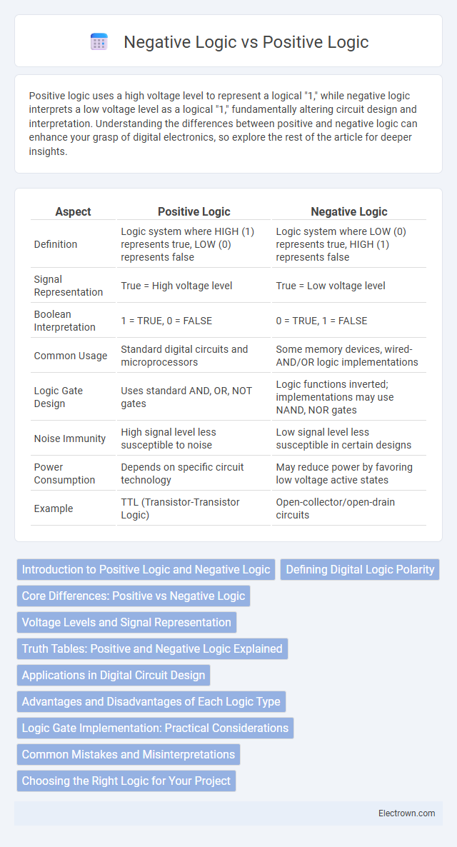
| Aspect | Positive Logic | Negative Logic |
|---|---|---|
| Definition | Logic system where HIGH (1) represents true, LOW (0) represents false | Logic system where LOW (0) represents true, HIGH (1) represents false |
| Signal Representation | True = High voltage level | True = Low voltage level |
| Boolean Interpretation | 1 = TRUE, 0 = FALSE | 0 = TRUE, 1 = FALSE |
| Common Usage | Standard digital circuits and microprocessors | Some memory devices, wired-AND/OR logic implementations |
| Logic Gate Design | Uses standard AND, OR, NOT gates | Logic functions inverted; implementations may use NAND, NOR gates |
| Noise Immunity | High signal level less susceptible to noise | Low signal level less susceptible in certain designs |
| Power Consumption | Depends on specific circuit technology | May reduce power by favoring low voltage active states |
| Example | TTL (Transistor-Transistor Logic) | Open-collector/open-drain circuits |
Introduction to Positive Logic and Negative Logic
Positive logic represents binary states where a higher voltage level corresponds to a logical "1," and a lower voltage level corresponds to a logical "0." Negative logic inverts this scheme, assigning a higher voltage level to a logical "0" and a lower voltage level to a logical "1." Understanding these logic conventions is crucial for designing digital circuits and interpreting signal behavior in systems like TTL and CMOS technologies.
Defining Digital Logic Polarity
Digital logic polarity defines how voltage levels correspond to binary values, with positive logic assigning a high voltage (commonly +5V or +3.3V) to represent a binary '1' and a low voltage (0V) for binary '0'. Negative logic inverts this convention, where a low voltage level represents a binary '1' and a high voltage represents a binary '0', impacting circuit design and interpretation of signals. Understanding these polarities is essential for designing and troubleshooting digital systems that rely on clear logic level definitions.
Core Differences: Positive vs Negative Logic
Positive logic represents true with a high voltage level (1) and false with a low voltage level (0), while negative logic inverts these assignments, representing true as low (0) and false as high (1). Core differences between positive and negative logic lie in their interpretation of voltage levels for logical states, impacting circuit design and logic gate behavior. Your choice between positive and negative logic influences signal processing and integration in digital electronics systems.
Voltage Levels and Signal Representation
Positive logic uses higher voltage levels to represent a logic 1 (true) and lower voltage levels for logic 0 (false), typically assigning a voltage close to the system's supply level as high. Negative logic inverts this convention by representing a logic 0 with a higher voltage and a logic 1 with a lower voltage, which can simplify circuit design in certain applications. Understanding these voltage level conventions helps you correctly interpret signal representations and design compatible digital circuits.
Truth Tables: Positive and Negative Logic Explained
Truth tables for positive logic assign a high voltage or logic '1' as true, while low voltage or logic '0' represents false, simplifying circuit design through direct correspondence to logical expressions. Negative logic inverses these assignments, interpreting low voltage or '0' as true and high voltage or '1' as false, effectively flipping the truth table outcomes for the same logical operations. Your understanding of both logic types enables accurate interpretation and design of digital systems where voltage levels define binary state representations.
Applications in Digital Circuit Design
Positive logic, where a high voltage level represents a binary 1, is extensively employed in digital circuit design for straightforward interpretation of signals and simplified circuit implementation in systems like microprocessors and memory devices. Negative logic, defining a low voltage level as binary 1, finds critical applications in noise-sensitive environments and power-efficient designs, often used in transistor-transistor logic (TTL) circuits and certain sensor interfacing. The choice between positive and negative logic directly impacts circuit reliability, noise immunity, and power consumption optimization in digital electronics.
Advantages and Disadvantages of Each Logic Type
Positive logic offers the advantage of intuitive understanding where a high voltage level represents a true or active state, simplifying circuit design and troubleshooting. Negative logic, using low voltage to indicate true, reduces power consumption in certain configurations and mitigates noise sensitivity in digital circuits. However, positive logic can be less power-efficient and more noise-prone, while negative logic may complicate circuit interpretation and require additional inversion steps in design.
Logic Gate Implementation: Practical Considerations
In logic gate implementation, positive logic uses high voltage to represent a logical "1," simplifying the design of TTL circuits and favoring compatibility with most digital components, while negative logic uses low voltage for "1," benefiting certain low-power applications. Positive logic gates typically exhibit faster switching speeds and easier fault detection, whereas negative logic circuits can reduce noise susceptibility by interpreting low voltage levels as active. Designers must consider these trade-offs alongside power consumption, noise margins, and component availability when choosing between positive and negative logic for practical digital system implementations.
Common Mistakes and Misinterpretations
Common mistakes in Positive Logic vs Negative Logic often arise from confusing active-high signals with active-low signals, leading to incorrect circuit behavior. Misinterpretations occur when assuming that a logical "1" always means "on" or "true" without considering signal inversion in Negative Logic systems. Your designs should explicitly clarify logic conventions to avoid errors in signal interpretation and ensure proper functionality.
Choosing the Right Logic for Your Project
Choosing the right logic for your project depends on the specific application requirements and the hardware design constraints. Positive logic simplifies interpretation by representing a high voltage level as logical "1," making it intuitive for most digital circuits, while negative logic inverts this convention, using low voltage levels as logical "1," which can reduce power consumption or noise susceptibility in some cases. Evaluating factors such as signal integrity, power efficiency, and compatibility with existing components ensures the selection of optimal logic for reliable and efficient system performance.
Positive Logic vs Negative Logic Infographic