Fan-out refers to the number of gate inputs that a single output can drive without signal degradation, while wire-OR is a logic configuration where multiple outputs are connected to a single line to perform an OR function electrically. Understanding the differences between fan-out and wire-OR helps optimize your circuit design for reliability and efficiency; read on to explore their specific applications and benefits.
Table of Comparison
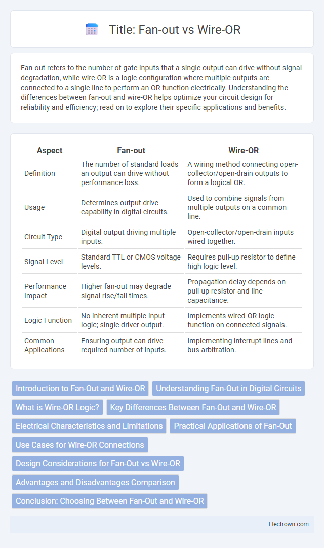
| Aspect | Fan-out | Wire-OR |
|---|---|---|
| Definition | The number of standard loads an output can drive without performance loss. | A wiring method connecting open-collector/open-drain outputs to form a logical OR. |
| Usage | Determines output drive capability in digital circuits. | Used to combine signals from multiple outputs on a common line. |
| Circuit Type | Digital output driving multiple inputs. | Open-collector/open-drain inputs wired together. |
| Signal Level | Standard TTL or CMOS voltage levels. | Requires pull-up resistor to define high logic level. |
| Performance Impact | Higher fan-out may degrade signal rise/fall times. | Propagation delay depends on pull-up resistor and line capacitance. |
| Logic Function | No inherent multiple-input logic; single driver output. | Implements wired-OR logic function on connected signals. |
| Common Applications | Ensuring output can drive required number of inputs. | Implementing interrupt lines and bus arbitration. |
Introduction to Fan-Out and Wire-OR
Fan-out refers to the maximum number of gate inputs that a single output can drive without degrading signal integrity, essential in digital circuit design for ensuring reliable operations. Wire-OR is a technique that connects multiple open-collector or open-drain outputs together to create a logical OR function without additional gates, commonly used in communication and control systems. Understanding the differences between fan-out and wire-OR helps you optimize signal distribution and logic simplification in your electronic designs.
Understanding Fan-Out in Digital Circuits
Fan-out in digital circuits refers to the maximum number of standard inputs that a single output can drive without signal degradation or timing issues. It is crucial to ensure that your circuit's output does not exceed the device's fan-out rating, preserving signal integrity and preventing voltage level distortions. Proper understanding of fan-out helps optimize circuit performance by balancing load demands and maintaining reliable logic levels.
What is Wire-OR Logic?
Wire-OR logic is a digital circuit configuration where multiple open-collector or open-drain outputs are connected directly to a common bus line, allowing any device to pull the line low and create a logical OR function through the wired connection. This arrangement enables multiple outputs to share a single line without the risk of output contention, as the line only goes high when all outputs are inactive, functioning as a wired logic OR gate. Wire-OR differs from fan-out in that fan-out describes the number of inputs a single output can drive, while wire-OR describes a method of combining outputs on a shared line to perform logical operations.
Key Differences Between Fan-Out and Wire-OR
Fan-out refers to the maximum number of gate inputs a single logic gate output can drive without signal degradation, whereas wire-OR is a technique that connects multiple open-collector or open-drain outputs to a single line for a logical OR function. Fan-out is limited by the electrical loading capacity and affects signal integrity, while wire-OR depends on the open-collector/open-drain configuration and passive pull-up resistors for proper operation. Understanding these differences is crucial for designing reliable digital circuits with appropriate signal driving and logical combination methods.
Electrical Characteristics and Limitations
Fan-out defines the maximum number of inputs a logic gate output can drive without signal degradation, directly affecting your circuit's loading and timing performance. Wire-OR configurations combine multiple open-collector or open-drain outputs on a single line, influencing voltage levels due to the pull-up resistor and shared bus capacitance. Electrical limitations of fan-out include increased propagation delay and reduced noise margins, while wire-OR constraints involve slower rise times and potential bus contention, requiring careful design consideration for reliable operation.
Practical Applications of Fan-Out
Fan-out is crucial in digital circuits for driving multiple inputs from a single output without degradation in signal integrity, commonly used in buffer amplification and signal branching. Your design benefits from improved reliability and timing when employing fan-out in memory address decoding, data bus distribution, and clock signal dissemination. This ensures effective load management and prevents signal distortion in complex integrated circuits.
Use Cases for Wire-OR Connections
Wire-OR connections are ideal for use in open-collector or open-drain circuits where multiple outputs need to be logically combined without interference. This configuration is commonly employed in interrupt lines, bus arbitration, and fault detection systems, allowing devices to assert signals without causing contention. Your designs benefit from wire-OR's simplicity in scenarios requiring multiple device signal merging with minimal hardware overhead.
Design Considerations for Fan-Out vs Wire-OR
Design considerations for fan-out focus on managing signal integrity by limiting the number of gates driven by a single output to prevent excessive load capacitance and delay. Wire-OR configurations require careful attention to ensure proper current sinking capabilities and avoid contention issues that can arise from multiple open-drain or open-collector outputs connected to a shared line. Selecting between fan-out and wire-OR depends on factors like propagation delay, power consumption, circuit complexity, and the specific logic family used in the design.
Advantages and Disadvantages Comparison
Fan-out provides the advantage of straightforward signal distribution from one output to multiple inputs, ensuring clear, strong signals with minimal delay, but it can increase load and power consumption as the number of connected inputs grows. Wire-OR offers a simpler bus-like connection without the need for active drivers, reducing hardware complexity and power use, yet it suffers from signal degradation, slower rise times, and potential contention issues when multiple devices drive the line simultaneously. Your choice between fan-out and wire-OR depends on balancing the need for signal integrity and speed against hardware simplicity and power efficiency.
Conclusion: Choosing Between Fan-Out and Wire-OR
Choosing between fan-out and wire-OR depends on the specific circuit requirements, such as signal integrity, load capacity, and power consumption. Fan-out is preferred for driving multiple inputs with isolated control and minimal interference, while wire-OR is suitable for simple, open-collector or open-drain configurations to combine signals logically. Evaluating the trade-offs in complexity, noise susceptibility, and application context is essential for optimal logic design.
Fan-out vs wire-OR Infographic