Series termination reduces signal reflections by placing a resistor in series with the signal line, optimizing signal integrity for high-speed digital circuits with minimal power loss. Parallel termination uses a resistor connected to a reference voltage at the load end to absorb reflections, improving signal quality in systems with strict impedance matching requirements; explore the article to understand which termination method suits your design best.
Table of Comparison
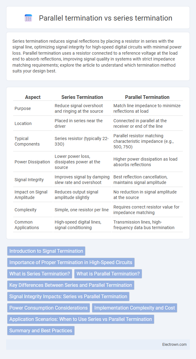
| Aspect | Series Termination | Parallel Termination |
|---|---|---|
| Purpose | Reduce signal overshoot and ringing at the source | Match line impedance to minimize reflections at load |
| Location | Placed in series near the driver | Connected in parallel at the receiver or end of the line |
| Typical Components | Series resistor (typically 22-33O) | Parallel resistor matching characteristic impedance (e.g., 50O, 75O) |
| Power Dissipation | Lower power loss, dissipates power at the source | Higher power dissipation as load absorbs reflections |
| Signal Integrity | Improves signal by damping slew rate and overshoot | Best reflection cancellation, maintains signal amplitude |
| Impact on Signal Amplitude | Reduces output signal amplitude slightly | No reduction in signal amplitude at the source |
| Complexity | Simple, one resistor per line | Requires correct resistor value for impedance matching |
| Common Applications | High-speed digital lines, signal conditioning | Transmission lines, high-frequency data bus termination |
Introduction to Signal Termination
Signal termination prevents reflections and signal integrity degradation by matching the transmission line impedance. Series termination places a resistor in line with the signal source to dampen reflections, ideal for short traces with controlled impedance. Parallel termination connects a resistor between the line and reference voltage at the load end, effectively absorbing signal reflections in high-speed or long-distance signal lines.
Importance of Proper Termination in High-Speed Circuits
Proper termination in high-speed circuits prevents signal reflections and ensures data integrity by matching impedance at the load. Series termination places a resistor in line with the signal path to dampen reflections at the source, while parallel termination uses a resistor at the load to absorb the signal energy. Choosing the right termination method is crucial to minimize electromagnetic interference and maintain signal quality in your high-frequency designs.
What is Series Termination?
Series termination is a technique used in high-speed digital circuits to reduce signal reflections by placing a resistor in series with the signal line near the driver. This resistor matches the output impedance of the driver to the transmission line, minimizing signal distortion and improving signal integrity. Series termination is especially effective for signals with short trace lengths and single-ended transmission lines.
What is Parallel Termination?
Parallel termination is a technique used in high-speed digital circuits to minimize signal reflections by placing a resistor equal to the characteristic impedance of the transmission line directly at the load end to ground or a reference voltage. This method effectively absorbs the signal energy and prevents it from bouncing back along the transmission line, ensuring signal integrity and reducing electromagnetic interference. Parallel termination is commonly employed in memory interfaces and data buses where precise impedance matching is critical for reliable data transmission.
Key Differences Between Series and Parallel Termination
Series termination involves placing a resistor in series with the signal line to match impedance and reduce reflections, primarily used in high-speed digital circuits. Parallel termination connects a resistor between the signal line and a reference voltage (often ground or supply voltage) at the receiving end to minimize signal reflections and preserve signal integrity. Series termination typically reduces power consumption and EMI, while parallel termination offers better signal quality and faster signal rise times but at higher power costs.
Signal Integrity Impacts: Series vs Parallel Termination
Series termination improves signal integrity by minimizing reflections and reducing overshoot through impedance matching at the source, which is effective for moderate frequency signals and shorter trace lengths. Parallel termination enhances signal integrity by providing a steady DC path to ground or Vcc, effectively damping reflections and maintaining signal quality over longer trace runs and higher frequencies. The choice between series and parallel termination depends on factors like signal frequency, trace length, power consumption, and the specific impedance characteristics of the transmission line.
Power Consumption Considerations
Series termination reduces power consumption by limiting signal overshoot and ringing, thereby minimizing unnecessary current flow during signal transitions. Parallel termination, while improving signal integrity, often increases static power consumption due to the continuous current drawn through the termination resistor to ground or supply voltage. Careful selection of termination method balances power efficiency with signal integrity, especially in high-frequency or low-power electronic designs.
Implementation Complexity and Cost
Series termination offers simpler implementation and lower cost by requiring only a single resistor placed near the driver output, minimizing PCB space and component count. Parallel termination demands more complex design considerations with resistors or termination networks placed at the receiving end, increasing component cost and board layout complexity due to the need for precise impedance matching. The higher material and design efforts in parallel termination make it costlier and more challenging compared to the straightforward approach of series termination.
Application Scenarios: When to Use Series vs Parallel Termination
Series termination suits applications where signal integrity is crucial in high-speed digital circuits, minimizing reflections on transmission lines. Parallel termination is ideal for bus systems or multi-drop configurations where impedance matching at the receiver end prevents signal overshoot and ringing. Choosing the right termination depends on your circuit layout, signal frequency, and load characteristics to optimize performance and reduce electromagnetic interference.
Summary and Best Practices
Series termination reduces signal reflections by placing a resistor close to the signal source, effectively matching the source impedance and minimizing ringing in high-speed digital circuits. Parallel termination involves placing a resistor at the load end, matching the line impedance to prevent signal overshoot and undershoot, commonly used when consistent voltage levels are critical. For best results, evaluate your signal frequency and line length; use series termination for shorter lines with moderate speed, and parallel termination for high-speed or sensitive data lines to ensure signal integrity and reduce electromagnetic interference.
Series termination vs parallel termination Infographic