Floating input pins can cause unpredictable behavior due to their susceptibility to noise and interference, making it essential to use pulled inputs for stable, defined logic levels in electronic circuits. Explore the rest of the article to understand how your choices impact circuit reliability and performance.
Table of Comparison
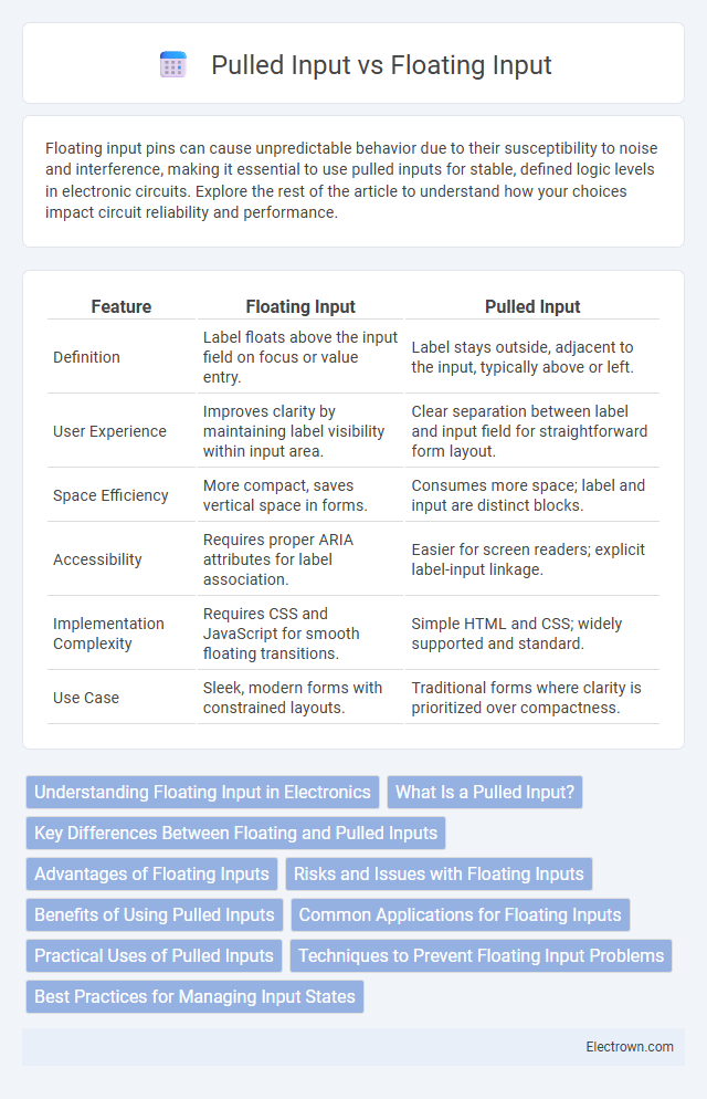
| Feature | Floating Input | Pulled Input |
|---|---|---|
| Definition | Label floats above the input field on focus or value entry. | Label stays outside, adjacent to the input, typically above or left. |
| User Experience | Improves clarity by maintaining label visibility within input area. | Clear separation between label and input field for straightforward form layout. |
| Space Efficiency | More compact, saves vertical space in forms. | Consumes more space; label and input are distinct blocks. |
| Accessibility | Requires proper ARIA attributes for label association. | Easier for screen readers; explicit label-input linkage. |
| Implementation Complexity | Requires CSS and JavaScript for smooth floating transitions. | Simple HTML and CSS; widely supported and standard. |
| Use Case | Sleek, modern forms with constrained layouts. | Traditional forms where clarity is prioritized over compactness. |
Understanding Floating Input in Electronics
Floating input in electronics refers to an input pin that is not connected to a defined voltage level, resulting in unpredictable or noisy signals due to interference or leakage currents. Pulled input involves using pull-up or pull-down resistors to ensure the input pin is always at a known logic level, preventing erratic behavior. Understanding floating input is crucial for designing stable circuits and avoiding false triggering or erratic operation in digital systems.
What Is a Pulled Input?
A pulled input is a type of digital input that uses a resistor connected to a voltage source or ground to ensure a defined logical state when the input switch is open or inactive, preventing the input pin from floating. Pull-up resistors connect the input to a high voltage level (usually 3.3V or 5V), while pull-down resistors connect it to ground, stabilizing the input reading. These resistors eliminate unpredictable behavior and false triggering by maintaining a default voltage level on the input pin.
Key Differences Between Floating and Pulled Inputs
Floating inputs occur when a microcontroller pin is left unconnected, causing unpredictable voltage levels and potential erratic behavior due to interference. Pulled inputs use internal or external resistors to connect the pin to a defined voltage level, ensuring stable and reliable readings by preventing the input from floating. Understanding these key differences helps you design circuits that avoid false triggers and improve overall system stability.
Advantages of Floating Inputs
Floating inputs provide enhanced signal sensitivity and accuracy by reducing common-mode noise and interference, making them ideal for precision measurement applications. They also offer greater flexibility in circuit design by allowing input signals to vary freely without reference to ground. This capability improves the overall performance of analog-to-digital converters and instrumentation amplifiers in complex electronic systems.
Risks and Issues with Floating Inputs
Floating inputs in electronic circuits create unpredictable voltage levels, leading to erratic behavior and increased susceptibility to noise and interference. This can cause false triggering, signal instability, and potential damage to components due to undefined logic states. Implementing pull-up or pull-down resistors ensures stable input conditions, significantly reducing these risks and enhancing overall circuit reliability.
Benefits of Using Pulled Inputs
Pulled inputs prevent undefined voltage levels by connecting the input pin to a stable voltage through a resistor, ensuring reliable and noise-free signal detection in digital circuits. Using pulled inputs improves the stability of microcontroller pins, reduces the risk of erratic behavior, and enhances overall circuit performance. Your designs benefit from increased signal integrity and simplified troubleshooting when employing pulled inputs.
Common Applications for Floating Inputs
Floating inputs are widely used in sensor interfaces and digital circuits where input signals must be detected without a predetermined logic state, such as in analog-to-digital converters and touchscreens. They allow the detection of environmental changes or external signals by sensing minute voltage variations without a default high or low level. Common applications include capacitive touch sensors, variable resistors, and input pins on microcontrollers that monitor analog or undefined signals requiring precise measurement.
Practical Uses of Pulled Inputs
Pulled inputs are crucial in digital circuits to ensure a defined logic level, preventing unpredictable behavior from floating inputs that can cause erratic switching or increased power consumption. Practical uses include connecting buttons or switches where an internal or external resistor maintains a default HIGH or LOW state, ensuring stable user input detection. Common implementations involve microcontroller GPIO pins configured with built-in pull-up or pull-down resistors to avoid noise and false readings.
Techniques to Prevent Floating Input Problems
To prevent floating input problems, use pull-up or pull-down resistors that connect the input pin to a defined voltage level, ensuring a stable logic state. Implementing internal or external resistors limits the input from floating, minimizing noise and undefined behavior in digital circuits. You can also configure microcontroller pins with built-in pull resistors if available, providing a reliable technique to maintain consistent input readings.
Best Practices for Managing Input States
Managing input states effectively improves circuit reliability by preventing undefined behavior. Best practices recommend avoiding floating inputs by using pull-up or pull-down resistors to ensure a defined logic level, reducing susceptibility to noise. Selecting the appropriate resistor value, typically between 10kO to 100kO, balances power consumption and noise immunity for stable input signal detection.
Floating input vs pulled input Infographic