GPIO pins provide simple digital input or output signals, allowing you to turn devices on or off, while PWM (Pulse Width Modulation) outputs a varying signal that simulates analog control, ideal for dimming LEDs or controlling motor speed. Discover how understanding the differences between GPIO and PWM can enhance your programming projects by reading the rest of this article.
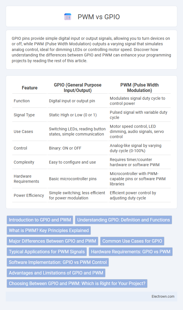
Table of Comparison
| Feature | GPIO (General Purpose Input/Output) | PWM (Pulse Width Modulation) |
|---|---|---|
| Function | Digital input or output pin | Modulates signal duty cycle to control power |
| Signal Type | Static High or Low (0 or 1) | Pulsed signal with variable duty cycle |
| Use Cases | Switching LEDs, reading button states, simple communication | Motor speed control, LED dimming, audio signals, servo control |
| Control | Binary: ON or OFF | Analog-like signal by varying duty cycle (0-100%) |
| Complexity | Easy to configure and use | Requires timer/counter hardware or software PWM |
| Hardware Requirements | Basic microcontroller pins | Microcontroller with PWM-capable pins or software PWM libraries |
| Power Efficiency | Simple switching; less efficient for power modulation | Efficient power control by adjusting duty cycle |
Introduction to GPIO and PWM
GPIO (General Purpose Input/Output) pins provide basic digital control by allowing devices to read or send binary signals, essential for simple on/off operations in electronics and microcontrollers. PWM (Pulse Width Modulation) enhances this by enabling variable control of power delivery through rapid switching, crucial for adjusting motor speeds or LED brightness with precision. Understanding the distinction between GPIO's straightforward digital signals and PWM's modulated pulses helps optimize your control over hardware components in embedded systems.
Understanding GPIO: Definition and Functions
General Purpose Input/Output (GPIO) pins serve as versatile digital interfaces on microcontrollers and single-board computers, allowing direct control and sensing of external components. GPIO pins can be programmed to function as either inputs, detecting voltage signals or button presses, or outputs, driving LEDs, relays, or other digital devices. Unlike Pulse Width Modulation (PWM) which generates variable duty cycle signals for analog-like control, GPIO primarily handles simple binary states for controlling or reading device status.
What is PWM? Key Principles Explained
PWM (Pulse Width Modulation) controls the amount of power delivered to electrical devices by rapidly switching the signal between on and off states, varying the duty cycle to adjust the effective voltage or current. Unlike a standard GPIO (General Purpose Input/Output) pin that simply provides a digital high or low output, PWM enables precise control of motors, LEDs, and other components by modulating signal timing. Understanding PWM's key principle--modulation of pulse duration within a fixed frequency--allows you to optimize your embedded systems for energy efficiency and performance.
Major Differences Between GPIO and PWM
GPIO (General Purpose Input/Output) pins provide simple binary control for devices, allowing digital signals to be either HIGH or LOW, essential for turning components on or off. PWM (Pulse Width Modulation) outputs vary the duty cycle of a signal to simulate analog values, enabling precise control of motor speed, LED brightness, and other devices requiring variable power. The key difference lies in GPIO's binary state control, while PWM allows modulation of signal power through timed pulses.
Common Use Cases for GPIO
GPIO pins are primarily used for digital input and output tasks such as reading sensor states, controlling LEDs, or toggling relays, making them essential for simple on/off control applications. Unlike PWM, which modulates signal duty cycles for devices like motor speed controllers or LED dimming, GPIO provides straightforward binary signals ideal for tasks requiring clear high or low states. You can rely on GPIO for direct hardware interfacing where precise timing modulation is not necessary.
Typical Applications for PWM Signals
PWM signals are widely used in controlling the brightness of LED lights, regulating motor speed in robotics, and managing power delivery in battery charging systems. These signals enable precise control over electrical devices by varying the duty cycle, making them essential in applications requiring efficient energy use and fine-tuned output. Understanding PWM's role helps you optimize hardware performance in embedded systems and IoT projects.
Hardware Requirements: GPIO vs PWM
GPIO (General Purpose Input/Output) pins require minimal hardware, typically involving simple digital signaling components like resistors and switches for basic input or output tasks. PWM (Pulse Width Modulation) demands hardware capable of generating precise timing signals, such as timers or dedicated PWM modules integrated into microcontrollers or specialized ICs. This difference means PWM hardware setups are more complex and often necessitate microcontroller support for accurate signal control and modulation.
Software Implementation: GPIO vs PWM Control
GPIO control relies on simple software instructions to toggle pins between high and low states, suitable for basic on/off tasks. PWM control requires more advanced software to generate precise pulse-width modulated signals for tasks like motor speed and LED brightness control. Your choice depends on whether your project demands straightforward digital signals or complex analog-like modulation via software.
Advantages and Limitations of GPIO and PWM
GPIO pins provide simple on/off control ideal for basic digital signals, offering straightforward implementation and low power consumption; however, they lack precision in controlling device speed or brightness. PWM signals allow fine-grained control of power delivery through varying duty cycles, enabling smooth operation of motors, LEDs, and other components; limitation arises from increased complexity and potential signal noise affecting sensitive applications. Your choice depends on whether you need simple digital switching (GPIO) or variable output control with timing precision (PWM).
Choosing Between GPIO and PWM: Which is Right for Your Project?
Choosing between GPIO and PWM depends on your project's control requirements: GPIO provides simple on/off signals ideal for basic tasks like turning LEDs or switches on and off, while PWM offers precise control by varying the duty cycle to manage motor speed, LED brightness, or servo positions. PWM generates a modulated signal that simulates analog output using digital pins, making it suitable for applications needing variable power levels. Understanding the specific needs of your hardware and desired output behavior ensures you select the optimal interface for efficient and reliable performance.
GPIO vs PWM Infographic