Open-drain outputs allow multiple devices to share a line safely by only pulling the line low, relying on external pull-up resistors to pull it high, making them ideal for wired-AND configurations and bus communication. Understanding the differences between open-drain and push-pull outputs will help you choose the right approach for your circuit design; explore the rest of the article to learn more about their applications and advantages.
Table of Comparison
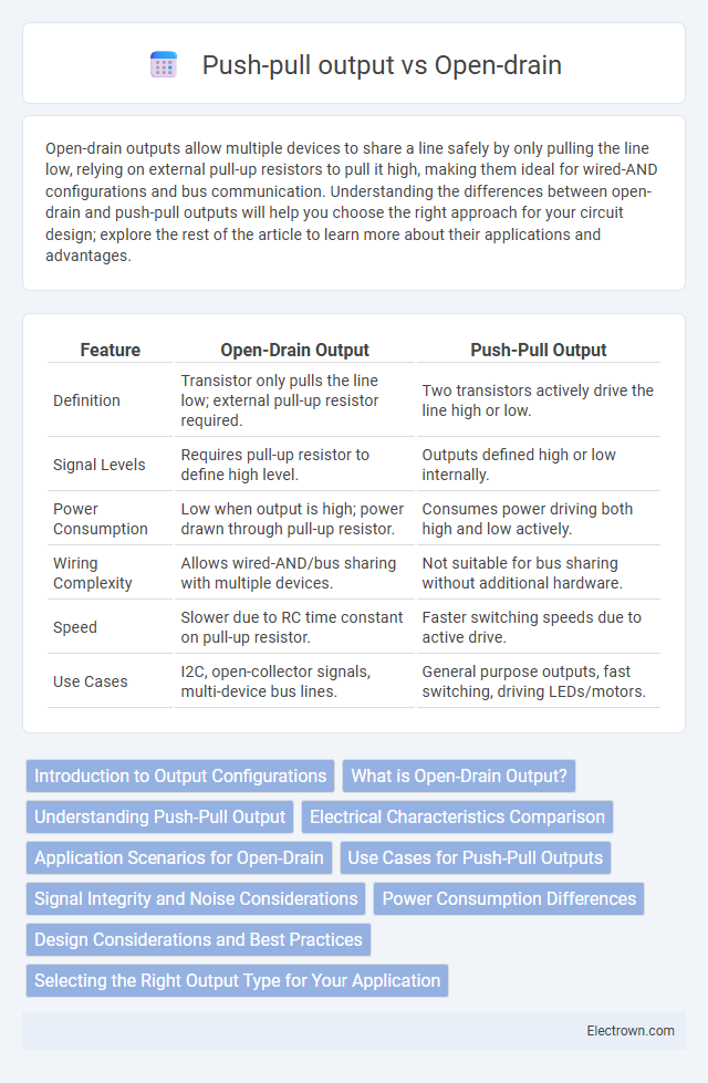
| Feature | Open-Drain Output | Push-Pull Output |
|---|---|---|
| Definition | Transistor only pulls the line low; external pull-up resistor required. | Two transistors actively drive the line high or low. |
| Signal Levels | Requires pull-up resistor to define high level. | Outputs defined high or low internally. |
| Power Consumption | Low when output is high; power drawn through pull-up resistor. | Consumes power driving both high and low actively. |
| Wiring Complexity | Allows wired-AND/bus sharing with multiple devices. | Not suitable for bus sharing without additional hardware. |
| Speed | Slower due to RC time constant on pull-up resistor. | Faster switching speeds due to active drive. |
| Use Cases | I2C, open-collector signals, multi-device bus lines. | General purpose outputs, fast switching, driving LEDs/motors. |
Introduction to Output Configurations
Open-drain and push-pull are common output configurations used in digital circuits to control signal flow and voltage levels. Open-drain outputs connect the pin to ground when active, requiring an external pull-up resistor to achieve a high logic level, ideal for wired-AND logic and multiple device sharing. Push-pull outputs actively drive the pin to both high and low states, offering faster switching times and stronger drive capabilities suitable for driving loads directly.
What is Open-Drain Output?
Open-drain output is a type of digital signal output used in microcontrollers and integrated circuits where the transistor's drain terminal is left open, allowing external devices to pull the line to a desired voltage level. This configuration requires an external pull-up resistor to achieve a high state and is ideal for wired-AND connections and bus systems. Understanding open-drain output helps You design circuits with flexible voltage levels and multiple devices sharing the same communication line.
Understanding Push-Pull Output
Push-pull output stages provide both sourcing and sinking current capabilities, enabling faster switching speeds and stronger drive strength for digital signals. This configuration actively drives the output high or low, improving signal integrity and reducing power consumption compared to open-drain outputs. Ideal for applications requiring precise voltage levels and high-speed data transmission, push-pull outputs minimize voltage drop and noise on communication lines.
Electrical Characteristics Comparison
Open-drain outputs rely on a transistor to pull the line low and require an external pull-up resistor to achieve a high state, resulting in slower rise times and higher power consumption due to the resistor. Push-pull outputs use complementary transistors to actively drive the line both high and low, providing faster switching speeds and lower output impedance. In terms of electrical characteristics, push-pull configurations offer stronger drive capability and better noise immunity, while open-drain outputs are preferred for wired-AND logic and level shifting applications.
Application Scenarios for Open-Drain
Open-drain outputs are ideal for wired-AND logic configurations, allowing multiple devices to share a common bus without conflict, commonly used in I2C communication protocols. These outputs excel in level shifting applications and enable safe interfacing with different voltage domains by relying on external pull-up resistors. Your choice of an open-drain output ensures robust and flexible connections in mixed-voltage or multi-device environments where precise control and collision avoidance are essential.
Use Cases for Push-Pull Outputs
Push-pull outputs are ideal for driving loads that require strong, bidirectional current flow, such as LEDs, motors, and speaker signals, where fast switching and full voltage swing are essential. They provide clear logic levels with both high and low states actively driven, ensuring noise immunity and efficient power delivery in digital circuits. Common applications include microcontroller GPIO pins directly controlling devices and high-speed communication interfaces requiring low output impedance.
Signal Integrity and Noise Considerations
Open-drain outputs improve signal integrity by allowing multiple devices to share a communication line without contention, reducing the risk of voltage level conflicts and signal distortion. Push-pull outputs actively drive the line both high and low, providing faster signal transitions but increasing the potential for noise and signal reflections due to simultaneous driving. In noisy environments, open-drain configurations paired with pull-up resistors help minimize electromagnetic interference and crosstalk, while push-pull outputs require careful impedance matching and termination to maintain signal quality.
Power Consumption Differences
Open-drain outputs consume less power during low output states because they only sink current when pulling the line to ground, minimizing static current draw. Push-pull outputs actively drive both high and low states, resulting in higher power consumption due to continuous current flow through the output transistors. Your choice impacts battery life and thermal performance, especially in low-power or energy-sensitive applications.
Design Considerations and Best Practices
Open-drain outputs require external pull-up resistors and are ideal for wired-AND logic and bus-sharing applications, while push-pull outputs drive both high and low states actively, ensuring faster switching and stronger signal integrity. Design considerations include power consumption, speed requirements, and complexity of external components; open-drain is preferred for low-power, multi-device buses, whereas push-pull suits high-speed, single-device communication. Best practices recommend careful pull-up resistor selection for open-drain circuits to balance rise time and power dissipation, and proper drive strength tuning in push-pull outputs to minimize electromagnetic interference and signal ringing.
Selecting the Right Output Type for Your Application
Open-drain outputs are ideal for wired-AND logic and multi-device communication on a shared bus, allowing external pull-up resistors to define voltage levels and prevent bus conflicts. Push-pull outputs deliver faster switching and stronger drive capabilities, making them suitable for high-speed, single-device applications requiring clear and robust signal transitions. Choosing between open-drain and push-pull depends on factors such as bus architecture, speed requirements, and the need for multiple devices to share the line safely.
Open-drain vs push-pull output Infographic