A 20mA loop offers precise current signaling commonly used in process control for reliable transmission over long distances, whereas a 10V loop provides a voltage signal that can be more susceptible to signal loss and interference in similar applications. Discover the key differences and find out which loop suits Your specific industrial needs by reading the rest of the article.
Table of Comparison
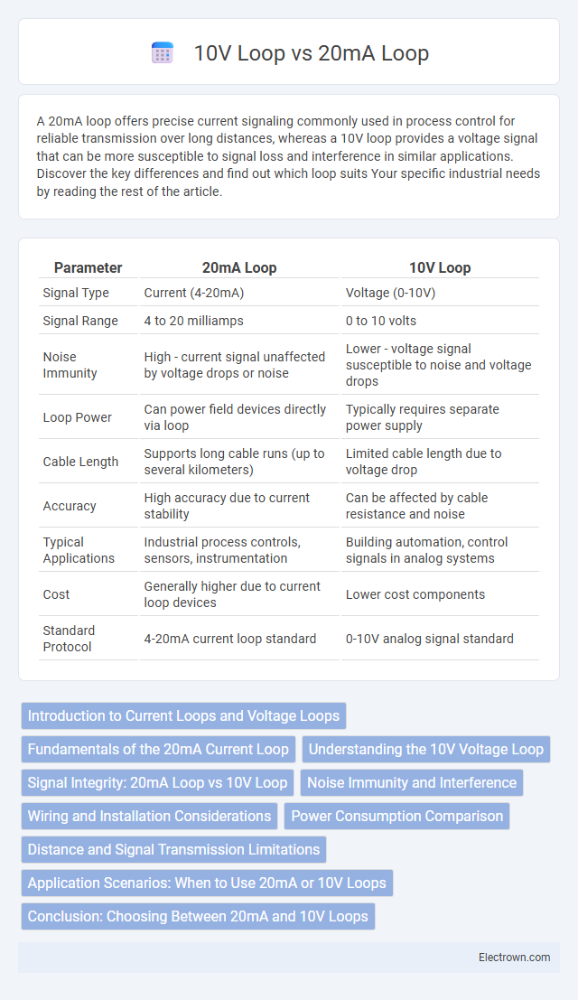
| Parameter | 20mA Loop | 10V Loop |
|---|---|---|
| Signal Type | Current (4-20mA) | Voltage (0-10V) |
| Signal Range | 4 to 20 milliamps | 0 to 10 volts |
| Noise Immunity | High - current signal unaffected by voltage drops or noise | Lower - voltage signal susceptible to noise and voltage drops |
| Loop Power | Can power field devices directly via loop | Typically requires separate power supply |
| Cable Length | Supports long cable runs (up to several kilometers) | Limited cable length due to voltage drop |
| Accuracy | High accuracy due to current stability | Can be affected by cable resistance and noise |
| Typical Applications | Industrial process controls, sensors, instrumentation | Building automation, control signals in analog systems |
| Cost | Generally higher due to current loop devices | Lower cost components |
| Standard Protocol | 4-20mA current loop standard | 0-10V analog signal standard |
Introduction to Current Loops and Voltage Loops
Current loops, such as the 20mA standard, transmit signals by varying electrical current within a closed circuit, offering noise resistance and long-distance reliability. Voltage loops like the 10V standard function by varying voltage levels, benefitting applications where fixed voltage references are crucial. Your choice depends on system compatibility, signal integrity requirements, and environmental conditions influencing measurement accuracy.
Fundamentals of the 20mA Current Loop
The 20mA current loop, commonly used in industrial process control, operates by transmitting analog signals as a constant current from 4 to 20mA, ensuring accurate and noise-resistant data communication over long distances. This current loop fundamentally relies on maintaining a consistent current flow regardless of voltage fluctuations, allowing precise sensor readings and control signals to be conveyed to PLCs or control systems. Compared to a 10V voltage loop, the 20mA current loop's immunity to voltage drop and electrical interference makes it the preferred standard for robust and reliable instrumentation feedback.
Understanding the 10V Voltage Loop
A 10V voltage loop typically operates by providing a stable and precise voltage signal ranging from 0 to 10 volts for transmitting sensor data or control signals. Unlike the 20mA current loop, which measures current to represent process variable values, the 10V voltage loop relies on voltage levels, making it more susceptible to voltage drops and noise over long distances. Proper shielding and calibration are essential to maintain signal integrity and accuracy in 10V voltage loop systems.
Signal Integrity: 20mA Loop vs 10V Loop
A 20mA current loop offers superior signal integrity compared to a 10V voltage loop, as it is less susceptible to voltage drops and electromagnetic interference over long cable runs. Current loops maintain consistent signal strength regardless of wire resistance, ensuring accurate and reliable transmission in industrial environments. In contrast, 10V voltage loops experience signal degradation due to voltage drops and noise, compromising measurement precision.
Noise Immunity and Interference
20mA current loops offer superior noise immunity compared to 10V voltage loops because current signals are less susceptible to voltage drops and electromagnetic interference over long distances. The constant current in 20mA loops ensures signal integrity even through resistive or inductive noise sources, while 10V loops can experience significant voltage fluctuation due to line resistance and external interference. Consequently, 20mA loops are preferred in industrial environments where reliable data transmission amidst electrical noise is critical.
Wiring and Installation Considerations
A 20mA current loop requires consistent current flow through its wiring, making it less susceptible to voltage drops over long distances and ideal for industrial sensor signals, while a 10V voltage loop depends on stable voltage levels, necessitating careful cable selection to prevent signal degradation. Using shielded, twisted-pair cables minimizes electromagnetic interference in both systems, but 20mA loops tolerate higher wire resistance better than 10V loops. For your installation, ensure proper grounding and choose wiring that matches the loop type to maintain signal integrity and reduce noise.
Power Consumption Comparison
A 20mA current loop typically consumes more power compared to a 10V voltage loop since power (P) is the product of current (I) and voltage (V), and current loops maintain continuous current flow leading to higher energy use. In a 20mA loop, power dissipation in the wiring and devices is greater, which can impact efficiency in battery-powered or low-energy systems. Your choice between these loops should consider power consumption requirements, especially for long-distance signal transmission or energy-sensitive applications.
Distance and Signal Transmission Limitations
20mA current loops effectively transmit signals over long distances, often exceeding several kilometers, because current remains constant regardless of wire resistance, ensuring signal integrity. In contrast, 10V voltage loops face significant voltage drop issues over extended distances due to wire resistance, limiting their effective range to a few hundred meters. Your choice should consider these transmission limitations, favoring 20mA loops for reliable long-distance signal monitoring.
Application Scenarios: When to Use 20mA or 10V Loops
20mA current loops are ideal for long-distance signal transmission in industrial environments due to their immunity to electrical noise and resistance variations. Use 10V voltage loops in low-power, short-distance applications where precise voltage levels are essential and signal degradation is minimal. Your choice depends on the specific requirements of signal integrity, distance, and power constraints in your control system.
Conclusion: Choosing Between 20mA and 10V Loops
Choosing between 20mA and 10V loops depends on the specific application requirements, with 20mA current loops offering superior noise immunity and longer transmission distances in industrial environments. Voltage loops, such as the 10V loop, are more susceptible to signal degradation and typically suit short-distance, low-noise settings. For precise sensor data transmission and robust communication, 20mA current loops are generally the preferred choice.
20mA loop vs 10V loop Infographic