Capacitive dividers offer frequency-dependent voltage scaling primarily used in high-frequency AC applications, while resistive dividers provide steady voltage division for DC or low-frequency signals with power dissipation considerations. Explore the rest of the article to understand which divider suits your circuit needs best.
Table of Comparison
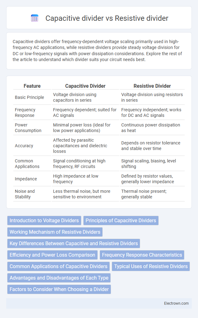
| Feature | Capacitive Divider | Resistive Divider |
|---|---|---|
| Basic Principle | Voltage division using capacitors in series | Voltage division using resistors in series |
| Frequency Response | Frequency dependent; suited for AC signals | Frequency independent; works for DC and AC signals |
| Power Consumption | Minimal power loss (ideal for low power applications) | Continuous power dissipation as heat |
| Accuracy | Affected by parasitic capacitances and dielectric losses | Depends on resistor tolerance and stable over time |
| Common Applications | Signal conditioning at high frequency, RF circuits | Signal scaling, biasing, level shifting |
| Impedance | High impedance at low frequency | Defined by resistor values, generally lower impedance |
| Noise and Stability | Less thermal noise, but more sensitive to environment | Thermal noise present; generally stable |
Introduction to Voltage Dividers
Voltage dividers are essential circuits that reduce voltage to desired levels using components like resistors or capacitors. A resistive divider uses two resistors to create a specific output voltage proportional to the input, ideal for DC signals. In contrast, a capacitive divider employs capacitors to divide AC voltages, making it suitable for applications involving signal frequency and impedance characteristics.
Principles of Capacitive Dividers
Capacitive dividers operate based on the principle of voltage division using reactance instead of resistance, where capacitors store energy in the electric field and their reactance decreases with increasing frequency. The voltage across each capacitor in a series circuit is inversely proportional to its capacitance, following the formula V = Q/C, allowing precise control of voltage division at high frequencies. This property makes capacitive dividers ideal for AC signal applications and frequency-dependent circuits, contrasting with resistive dividers that rely on resistance for voltage division in DC and low-frequency scenarios.
Working Mechanism of Resistive Dividers
Resistive dividers function by using two or more resistors connected in series to produce an output voltage that is a fraction of the input voltage, determined by the ratio of the resistances. Your circuit's voltage is tapped from the node between resistors, where the voltage drop across each resistor follows Ohm's law, enabling precise voltage scaling. This mechanism makes resistive dividers ideal for signal level adjustment and sensor voltage scaling in low-frequency applications.
Key Differences Between Capacitive and Resistive Dividers
Capacitive dividers use capacitors to split voltage based on reactance, offering frequency-dependent voltage division ideal for AC signals and high-frequency applications. Resistive dividers rely on fixed resistors to provide a stable, frequency-independent voltage ratio suitable for DC and low-frequency circuits. Your choice between these dividers depends on whether you need precise control over voltage at varying frequencies or consistent division regardless of signal frequency.
Efficiency and Power Loss Comparison
Capacitive dividers offer higher efficiency with minimal power loss compared to resistive dividers, as capacitors ideally consume no static power while resistors continuously dissipate energy as heat. Resistive dividers result in significant power loss proportional to current through resistance, reducing overall circuit efficiency, especially at low voltage levels. Your choice of a capacitive divider can lead to improved energy savings and longer battery life in low-current applications.
Frequency Response Characteristics
Capacitive dividers exhibit frequency-dependent behavior with impedance decreasing as frequency increases, making them ideal for high-frequency applications due to minimal signal loss and phase shift. Resistive dividers maintain consistent attenuation across a wide frequency range but introduce thermal noise and power dissipation, potentially affecting low-frequency accuracy. Understanding the frequency response characteristics of both ensures optimal performance in your signal conditioning and measurement circuits.
Common Applications of Capacitive Dividers
Capacitive dividers are commonly used in high-frequency circuits such as RF signal processing, antenna tuning, and impedance matching due to their low power loss and minimal noise generation. Unlike resistive dividers, they excel in applications requiring AC voltage division without dissipating significant energy, making them ideal for voltage measurement in oscilloscopes and communication systems. Understanding the benefits of capacitive dividers can enhance your circuit design, especially in precision high-frequency environments.
Typical Uses of Resistive Dividers
Resistive dividers are commonly used in analog circuits for voltage scaling, signal attenuation, and biasing applications, providing a precise and stable output voltage. You will often find them in sensor interfaces, reference voltage generation, and audio volume controls, where consistent linear division of voltage is crucial. Their simplicity and reliability make them ideal for low-frequency or DC voltage division tasks compared to capacitive dividers.
Advantages and Disadvantages of Each Type
Capacitive dividers offer high-frequency response and minimal power loss due to their reactive nature, making them ideal for AC signal applications, but they are sensitive to frequency variations and have limited DC measurement capability. Resistive dividers provide stable and accurate voltage division for DC and low-frequency signals with simplicity and linearity, but they dissipate power as heat and can introduce loading effects on the source. Choosing between capacitive and resistive dividers depends on the specific application requirements such as frequency range, power efficiency, and measurement accuracy.
Factors to Consider When Choosing a Divider
When choosing between a capacitive divider and a resistive divider, consider factors such as frequency response, power consumption, and signal integrity. Capacitive dividers excel in high-frequency applications due to their low power dissipation and minimal thermal noise, while resistive dividers offer simplicity and stable performance in low-frequency or DC circuits. The choice depends on the specific application requirements, including impedance matching, signal bandwidth, and accuracy constraints.
Capacitive divider vs Resistive divider Infographic