Line commutated converters rely on the AC supply voltage to turn off the thyristors, making them suitable for applications with a strong grid connection but limited in controlling output frequency. Force commutated converters use external circuits to turn off thyristors, allowing more precise control over power conversion regardless of grid conditions. Explore the article to understand which converter type best suits your power system needs.
Table of Comparison
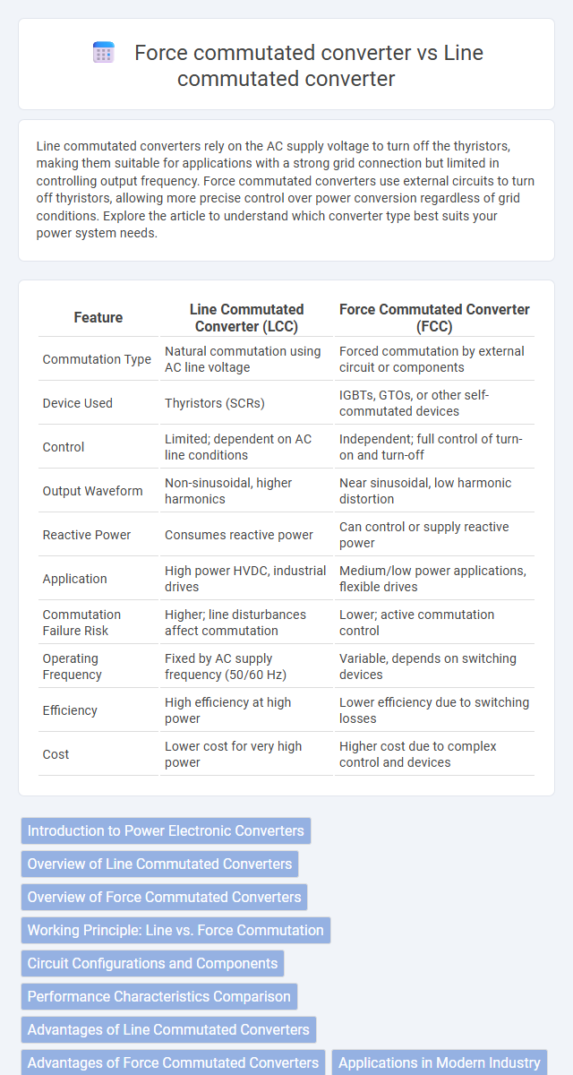
| Feature | Line Commutated Converter (LCC) | Force Commutated Converter (FCC) |
|---|---|---|
| Commutation Type | Natural commutation using AC line voltage | Forced commutation by external circuit or components |
| Device Used | Thyristors (SCRs) | IGBTs, GTOs, or other self-commutated devices |
| Control | Limited; dependent on AC line conditions | Independent; full control of turn-on and turn-off |
| Output Waveform | Non-sinusoidal, higher harmonics | Near sinusoidal, low harmonic distortion |
| Reactive Power | Consumes reactive power | Can control or supply reactive power |
| Application | High power HVDC, industrial drives | Medium/low power applications, flexible drives |
| Commutation Failure Risk | Higher; line disturbances affect commutation | Lower; active commutation control |
| Operating Frequency | Fixed by AC supply frequency (50/60 Hz) | Variable, depends on switching devices |
| Efficiency | High efficiency at high power | Lower efficiency due to switching losses |
| Cost | Lower cost for very high power | Higher cost due to complex control and devices |
Introduction to Power Electronic Converters
Power electronic converters play a crucial role in controlling electrical energy flow in modern power systems, with Line Commutated Converters (LCCs) and Force Commutated Converters (FCCs) being two primary types. LCCs rely on the AC line voltage for commutation, making them suitable for high-power applications but dependent on a strong grid, while FCCs use forced switching devices like IGBTs for intentional commutation, enabling greater control and operation in weak or isolated grids. These differences impact converter efficiency, harmonic generation, and suitability for HVDC transmission and industrial motor drives.
Overview of Line Commutated Converters
Line Commutated Converters (LCC) utilize the AC supply voltage for switching off power semiconductor devices, relying on the natural zero crossing of current to achieve commutation. These converters predominantly employ thyristors and are widely used in high-power applications such as HVDC transmission and industrial drives due to their robustness and efficiency. The key limitations include dependency on a strong AC system and the generation of significant harmonic distortion, necessitating extensive filtering and reactive power compensation.
Overview of Force Commutated Converters
Force commutated converters utilize external commutation methods, such as forced commutation circuits or capacitor banks, to turn off thyristors independently of the AC line voltage zero crossing. These converters provide greater control over the switching process, enabling operation in applications requiring rapid and bidirectional current control, including high-frequency inverters and DC motor drives. Unlike line commutated converters which rely on the AC supply waveform for commutation, force commutated converters achieve improved performance in terms of switching speed, voltage regulation, and reduced harmonic distortion.
Working Principle: Line vs. Force Commutation
Line commutated converters operate by using the AC supply voltage waveform to naturally force the thyristors to turn off when the input voltage polarity reverses, relying on the line voltage zero crossing for commutation. Force commutated converters employ an external circuit, such as a resonant circuit or forced commutation circuit, to actively turn off the thyristors independent of the supply voltage, enabling operation with DC sources or at controlled switching times. This fundamental difference in commutation method impacts their applicability, with line commutated converters suited for AC line-tied applications and force commutated converters ideal for DC or regenerative braking systems.
Circuit Configurations and Components
Line commutated converters primarily use thyristors controlled by the AC supply waveform, requiring a large inductive load or a synchronous source for commutation, and their circuit configuration includes a simple diode-thyristor bridge with fewer passive components. Force commutated converters employ self-commutated devices like IGBTs or GTOs that need auxiliary commutation circuits such as capacitors, inductors, and snubber networks to turn off the device, resulting in more complex circuit topologies. The inclusion of forced commutation elements enables operation with DC or weak AC supplies, making the converter configuration more versatile but also more component-intensive.
Performance Characteristics Comparison
Line commutated converters rely on the AC supply voltage to turn off their thyristors, resulting in slower switching speeds and higher harmonic distortion compared to force commutated converters, which use auxiliary circuits to actively turn off devices and achieve faster switching. Force commutated converters exhibit superior performance in applications requiring rapid switching, better power factor control, and lower harmonic generation, making them suitable for high-frequency and dynamic loads. Your choice between these converters depends on specific performance requirements such as switching speed, harmonic content, and power quality.
Advantages of Line Commutated Converters
Line Commutated Converters (LCC) offer higher efficiency and are well-suited for high-power applications such as HVDC transmission due to their ability to handle large currents with low conduction losses. Their robust design ensures reliable operation under heavy load conditions and they utilize thyristors, which are cost-effective and have proven technology. You benefit from their well-established industry use, making maintenance and component availability more accessible.
Advantages of Force Commutated Converters
Force commutated converters offer the advantage of independent control of the output voltage and current, enabling adjustable power conversion suitable for various applications. These converters operate without relying on the AC supply zero crossing, allowing operation under both continuous and discontinuous current conditions, which enhances flexibility and system stability. Their capability to switch at any desired time improves efficiency and reduces harmonic distortion compared to line commutated converters.
Applications in Modern Industry
Line commutated converters are widely used in high-voltage direct current (HVDC) power transmission and industrial motor drives due to their efficiency in handling large power loads. Force commutated converters find applications in adjustable speed drives and aerospace electronics where precise control and rapid switching are critical. Understanding these differences helps optimize Your choice for applications requiring either robust power handling or fast, flexible control.
Key Differences and Selection Criteria
Line commutated converters rely on the AC supply voltage to turn off thyristors naturally, making them suitable for high-power industrial applications with steady AC sources. Force commutated converters use external circuits to switch off thyristors, providing greater control and suitability for DC motor drives and applications requiring rapid switching. Your selection depends on factors like power quality, control complexity, and load type, with line commutated preferred for simplicity and force commutated for dynamic performance.
Line commutated vs Force commutated converter Infographic