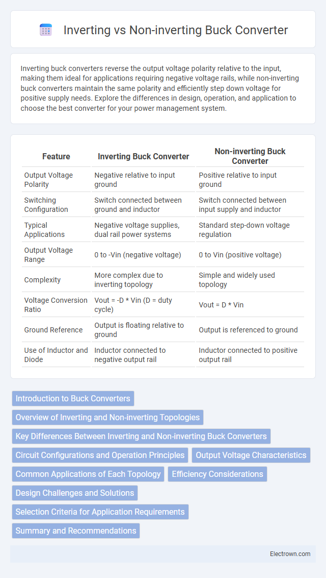
Inverting buck converters reverse the output voltage polarity relative to the input, making them ideal for applications requiring negative voltage rails, while non-inverting buck converters maintain the same polarity and efficiently step down voltage for positive supply needs. Explore the differences in design, operation, and application to choose the best converter for your power management system.
Table of Comparison
| Feature | Inverting Buck Converter | Non-inverting Buck Converter |
|---|---|---|
| Output Voltage Polarity | Negative relative to input ground | Positive relative to input ground |
| Switching Configuration | Switch connected between ground and inductor | Switch connected between input supply and inductor |
| Typical Applications | Negative voltage supplies, dual rail power systems | Standard step-down voltage regulation |
| Output Voltage Range | 0 to -Vin (negative voltage) | 0 to Vin (positive voltage) |
| Complexity | More complex due to inverting topology | Simple and widely used topology |
| Voltage Conversion Ratio | Vout = -D * Vin (D = duty cycle) | Vout = D * Vin |
| Ground Reference | Output is floating relative to ground | Output is referenced to ground |
| Use of Inductor and Diode | Inductor connected to negative output rail | Inductor connected to positive output rail |
Introduction to Buck Converters
Buck converters are widely used DC-DC power converters designed to step down voltage efficiently while maintaining high power density and low heat dissipation. Inverting buck converters output a voltage opposite in polarity to the input, useful in applications requiring negative voltage rails, while non-inverting buck converters maintain the same polarity as the input, making them ideal for most standard power supply needs. Your choice between these depends on the specific voltage polarity and regulation requirements of your electronic system.
Overview of Inverting and Non-inverting Topologies
Inverting and non-inverting buck converters differ primarily in output polarity relative to the input voltage; inverting converters produce a negative output voltage, while non-inverting converters maintain a positive output voltage. The non-inverting buck converter topology is widely used for step-down DC-DC conversion, providing efficient voltage regulation with minimal components. Your choice between these topologies depends on the required output polarity and application needs, with inverting converters suited for negative voltage rails and non-inverting converters for standard positive voltage rails.
Key Differences Between Inverting and Non-inverting Buck Converters
Inverting buck converters produce a negative output voltage relative to the input, while non-inverting buck converters provide a positive output voltage lower than the input. The switching topology differs; inverting converters use an inverting switch configuration that flips polarity, whereas non-inverting converters employ a high-side switch that maintains output polarity. Efficiency varies with load and design, as non-inverting buck converters generally exhibit higher efficiency due to reduced conduction losses and simpler control schemes.
Circuit Configurations and Operation Principles
The inverting buck converter uses a configuration where the output voltage polarity is opposite to the input, employing a switching element connected to ground and an inductor-capacitor network to store and transfer energy. Non-inverting buck converters maintain the same output polarity as the input, utilizing a high-side switch and diode in a topology that steps down voltage efficiently with reduced complexity. Understanding these distinct circuit configurations and operation principles helps optimize your power supply design for specific voltage polarity and regulation requirements.
Output Voltage Characteristics
Inverting buck converters produce a negative output voltage relative to the ground, which is useful for applications requiring negative supply rails, while non-inverting buck converters provide a positive output voltage less than the input voltage. Output voltage of inverting converters is determined by the duty cycle but inverted in polarity, following Vout = -D * Vin, whereas non-inverting buck converters have Vout = D * Vin, with D representing the duty cycle. The choice between the two depends on the polarity and magnitude requirements of the load, influencing circuit topology and feedback control design.
Common Applications of Each Topology
Non-inverting buck converters are commonly used in applications requiring efficient step-down voltage conversion with stable output, such as powering microcontrollers, battery-operated devices, and LED drivers. Inverting buck converters are typically employed in scenarios where a negative voltage relative to the input ground is needed, including dual power supply systems, audio amplifiers, and signal processing equipment. Your choice between these topologies depends on whether the application demands positive or negative regulated output voltage.
Efficiency Considerations
Inverting buck converters typically exhibit slightly lower efficiency compared to non-inverting buck converters due to additional power losses caused by the inverting stage and associated components. Non-inverting buck converters achieve higher efficiency by minimizing voltage drop and reducing switching losses in the power path, making them more suitable for applications where power conservation is critical. When optimizing your power supply design, understanding these efficiency differences helps maximize battery life and thermal management.
Design Challenges and Solutions
Inverting buck converters face design challenges such as handling negative output voltage, which requires careful selection of switches and control strategies to maintain stability and minimize switching losses. Non-inverting buck converters simplify layout by providing a positive output voltage but demand efficient gate drive techniques and EMI mitigation to optimize performance. Solutions include using synchronous rectification and custom control loops tailored to the converter topology to improve efficiency and transient response.
Selection Criteria for Application Requirements
Inverting and non-inverting buck converters differ primarily in output voltage polarity and complexity, impacting selection based on application requirements. Non-inverting buck converters provide a positive output voltage less than the input and are preferred for simple step-down needs with high efficiency and low noise. You should choose inverting buck converters when a negative output voltage is required, such as in bipolar power supply applications, despite their typically higher design complexity and potential for increased noise.
Summary and Recommendations
Inverting buck converters produce a negative output voltage relative to the input, ideal for applications requiring voltage polarity reversal, while non-inverting buck converters maintain the same polarity with efficient step-down voltage regulation. Your choice depends on the required output polarity and complexity; non-inverting converters offer simplicity and improved efficiency for standard power supply needs, whereas inverting types suit specialized circuits needing negative voltages. For general DC-DC step-down applications, recommend non-inverting buck converters due to their widespread compatibility and simpler design.
Inverting vs Non-inverting buck converter Infographic