Return loss measures the amount of signal reflected back towards the source due to impedance mismatches, while insertion loss quantifies the signal power lost as it passes through a component or system. Understanding the differences and implications of these losses can significantly improve Your system's performance; continue reading to explore how each impacts communication efficiency.
Table of Comparison
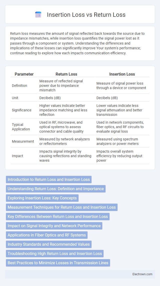
| Parameter | Return Loss | Insertion Loss |
|---|---|---|
| Definition | Measure of reflected signal power due to impedance mismatch | Measure of signal power loss through a device or component |
| Unit | Decibels (dB) | Decibels (dB) |
| Significance | Higher values indicate better impedance matching and less reflection | Lower values indicate less signal attenuation and better transmission |
| Typical Application | Used in RF, microwave, and optical systems to assess connector and cable quality | Used in network components, fiber optics, and RF circuits to evaluate signal loss |
| Measurement | Measured by network analyzers or reflectometers | Measured using spectrum analyzers or power meters |
| Impact | Impacts signal integrity by causing reflections and standing waves | Impacts overall system efficiency by reducing output power |
Introduction to Return Loss and Insertion Loss
Return Loss measures the amount of signal reflected back toward the source due to impedance mismatches in a transmission line, expressed in decibels (dB). Insertion Loss quantifies the reduction in signal power as it passes through a device or medium, also measured in decibels, indicating how much signal your system loses during transmission. Understanding both Return Loss and Insertion Loss is essential for optimizing the performance and efficiency of communication systems and minimizing signal degradation.
Understanding Return Loss: Definition and Importance
Return loss measures the amount of signal reflected back toward the source due to impedance mismatches in a transmission line, expressed in decibels (dB). High return loss indicates better signal transmission with minimal reflections, which is critical for maintaining signal integrity in communication systems. Understanding return loss helps you optimize network performance by ensuring efficient power transfer and reducing potential signal degradation.
Exploring Insertion Loss: Key Concepts
Insertion loss measures the reduction in signal power as it passes through a device or transmission line, expressed in decibels (dB), and is crucial for evaluating system efficiency and signal integrity. Return loss quantifies the amount of signal reflected back toward the source due to impedance mismatches, providing insight into connection quality and potential signal degradation. Understanding insertion loss helps you optimize your system by minimizing power loss and ensuring smoother signal transmission.
Measurement Techniques for Return Loss and Insertion Loss
Return loss measurement techniques typically involve using a network analyzer to send a signal through the device under test and analyzing the reflected power to determine signal reflections. Insertion loss is measured by comparing the input and output power levels across a component, often using a power meter or a vector network analyzer to quantify the signal attenuation. Your choice of measurement method depends on the required accuracy and the specific frequency range of the system.
Key Differences Between Return Loss and Insertion Loss
Return Loss measures the amount of signal reflected back toward the source, indicating impedance mismatches in a transmission line, typically expressed in decibels (dB). Insertion Loss quantifies the loss of signal power resulting from the insertion of a device or component in a transmission path, also measured in decibels. The key differences lie in their focus: Return Loss assesses signal reflection and impedance matching, while Insertion Loss evaluates signal attenuation caused by the device itself.
Impact on Signal Integrity and Network Performance
Return loss measures signal reflections caused by impedance mismatches, directly affecting signal integrity by increasing noise and potential data errors. Insertion loss quantifies signal power reduction as it passes through a component, impacting network performance by lowering signal strength and limiting transmission distance. Optimizing both return loss and insertion loss is crucial for maintaining your network's reliability and minimizing signal degradation.
Applications in Fiber Optics and RF Systems
Return loss measures the amount of reflected signal in fiber optics and RF systems, indicating signal quality and connector performance, while insertion loss quantifies signal power loss through components or cables. In fiber optics, high return loss ensures minimal reflection at splices and connectors, critical for maintaining data integrity in high-speed networks. In RF systems, low insertion loss optimizes signal transmission efficiency, improving antenna performance and reducing system noise in wireless communication and radar applications.
Industry Standards and Recommended Values
Return loss and insertion loss are critical parameters in RF and telecommunications industry standards, with organizations such as IEEE and ITU specifying recommended values to ensure signal integrity and device performance. Return loss is typically recommended to be greater than 20 dB to minimize signal reflections, while insertion loss should be as low as possible, commonly below 1 dB, to maintain efficient power transfer. Adherence to these standards guarantees optimal performance in applications such as fiber optics, coaxial cables, and connector assemblies.
Troubleshooting High Return Loss and Insertion Loss
High return loss indicates significant signal reflection often caused by impedance mismatches, damaged connectors, or faulty cables, requiring thorough inspection and replacement of affected components. Elevated insertion loss signifies excessive signal attenuation typically due to cable degradation, poor splices, or connector contamination, demanding cleaning, repair, or cable rerouting. Employing advanced testing equipment such as optical time-domain reflectometers (OTDR) and vector network analyzers helps pinpoint fault locations, enhancing troubleshooting accuracy for both return loss and insertion loss issues.
Best Practices to Minimize Losses in Transmission Lines
Minimizing return loss and insertion loss in transmission lines requires selecting high-quality, low-loss materials such as PTFE or polyethylene dielectrics and ensuring precise impedance matching throughout the system. Maintaining proper cable termination, using connectors with minimal VSWR, and implementing thorough cable routing to avoid sharp bends or physical damage significantly reduce signal reflections and attenuation. Your overall system performance improves by regularly testing return loss with a network analyzer and optimizing installation practices to maintain consistent characteristic impedance and minimize discontinuities.
Return Loss vs Insertion Loss Infographic