Transmission lines distribute electrical signals along a length with distributed inductance, capacitance, and resistance, ideal for high-frequency or long-distance applications where signal integrity matters. Understanding these differences can enhance your circuit design; explore the rest of the article to learn how to choose the right model for your needs.
Table of Comparison
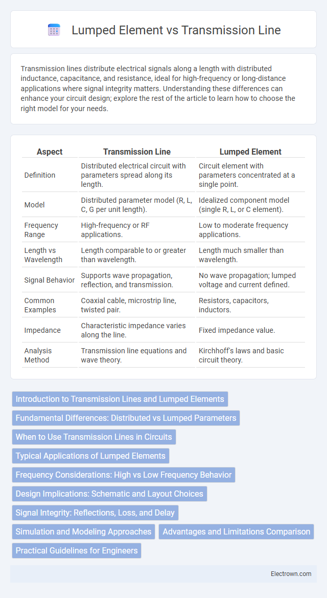
| Aspect | Transmission Line | Lumped Element |
|---|---|---|
| Definition | Distributed electrical circuit with parameters spread along its length. | Circuit element with parameters concentrated at a single point. |
| Model | Distributed parameter model (R, L, C, G per unit length). | Idealized component model (single R, L, or C element). |
| Frequency Range | High-frequency or RF applications. | Low to moderate frequency applications. |
| Length vs Wavelength | Length comparable to or greater than wavelength. | Length much smaller than wavelength. |
| Signal Behavior | Supports wave propagation, reflection, and transmission. | No wave propagation; lumped voltage and current defined. |
| Common Examples | Coaxial cable, microstrip line, twisted pair. | Resistors, capacitors, inductors. |
| Impedance | Characteristic impedance varies along the line. | Fixed impedance value. |
| Analysis Method | Transmission line equations and wave theory. | Kirchhoff's laws and basic circuit theory. |
Introduction to Transmission Lines and Lumped Elements
Transmission lines are specialized structures designed to carry electromagnetic signals over distances with minimal distortion, characterized by distributed parameters such as inductance, capacitance, resistance, and conductance per unit length. Lumped elements, by contrast, represent idealized circuit components like resistors, capacitors, and inductors assumed to have all of their properties concentrated at a single point, making them suitable for analyzing circuits where the physical dimensions are much smaller than the signal wavelength. Understanding the differences in behavior and modeling between transmission lines and lumped elements is crucial for accurately designing and analyzing high-frequency circuits and communication systems.
Fundamental Differences: Distributed vs Lumped Parameters
Transmission lines are characterized by distributed parameters, where resistance, inductance, capacitance, and conductance are spread continuously along the line's length, impacting signal propagation and wave behavior. Lumped elements, in contrast, concentrate these parameters at discrete points, simplifying circuit analysis by assuming instantaneous voltage and current changes. Understanding these fundamental differences is crucial for designing systems where Your signal integrity and frequency response depend on accurate modeling of either distributed or lumped effects.
When to Use Transmission Lines in Circuits
Transmission lines are used in circuits when the signal wavelength is comparable to the physical length of the circuit elements, typically at high frequencies above 100 MHz, where distributed effects such as impedance, phase shift, and signal reflections become significant. Lumped elements are suitable for low-frequency applications where the circuit dimensions are much smaller than the signal wavelength, allowing components like resistors, capacitors, and inductors to be treated as ideal point elements. Transmission lines ensure proper impedance matching and minimize signal distortion in RF, microwave, and high-speed digital circuits.
Typical Applications of Lumped Elements
Lumped elements are commonly utilized in low-frequency circuit designs such as filters, amplifiers, and oscillator circuits due to their simple modeling and predictable behavior. These components effectively represent inductors, capacitors, and resistors in integrated circuits and printed circuit boards, making them ideal for compact analog and digital applications. Your design benefits from lumped elements when precise voltage, current control, and simplified analysis are essential at frequencies where wave propagation effects are negligible.
Frequency Considerations: High vs Low Frequency Behavior
Transmission lines behave differently at high frequencies where signal wavelength becomes comparable to the line length, causing reflections and impedance mismatches critical for RF design. Lumped elements assume idealized components with no distributed effects, accurately modeling low-frequency circuits where wavelength is much larger than component size. Understanding these frequency considerations helps optimize Your circuit's performance by selecting transmission lines for high-frequency applications and lumped elements for low-frequency scenarios.
Design Implications: Schematic and Layout Choices
Transmission lines require careful impedance matching and length consideration in both schematic and layout to minimize signal reflection and loss, often necessitating distributed element modeling and precise trace geometries. Lumped element designs simplify schematic representation using discrete components like resistors, capacitors, and inductors, allowing more straightforward layout with standard PCB footprints but may suffer from parasitic effects at high frequencies. Choosing between transmission line and lumped element approaches impacts board area, component placement, and signal integrity, particularly in high-speed or RF applications.
Signal Integrity: Reflections, Loss, and Delay
Transmission lines maintain signal integrity by minimizing reflections through impedance matching, controlling loss via conductor and dielectric properties, and managing delay with precise physical length and propagation velocity. Lumped elements, while simpler, often introduce undesired reflections and signal degradation at high frequencies due to their discrete nature and parasitic effects. Proper transmission line design ensures consistent signal propagation, critical for high-speed and high-frequency electronic systems.
Simulation and Modeling Approaches
Transmission line modeling employs distributed parameter models capturing frequency-dependent signal propagation and reflections, ideal for high-frequency or long-distance simulations. Lumped element simulation uses simplified circuit components like resistors, capacitors, and inductors, assuming uniform voltage and current, making it efficient for low-frequency or small-scale circuits. Your choice depends on accuracy requirements and computational resources, with transmission line models providing detailed wave behavior while lumped elements offer faster, approximate simulations.
Advantages and Limitations Comparison
Transmission lines excel in high-frequency signal propagation with minimal distortion due to distributed parameters, offering precise impedance control and reduced signal loss over long distances. Lumped elements are advantageous for low-frequency circuits where component values can be treated as discrete, simplifying analysis and design but introducing inaccuracies at higher frequencies due to parasitic effects. Transmission lines require complex modeling and can be bulky, while lumped elements provide compact, easy-to-integrate solutions limited by frequency-dependent performance and reduced accuracy in high-frequency applications.
Practical Guidelines for Engineers
Transmission lines handle signal propagation over distances exceeding a fraction of the signal's wavelength, requiring engineers to consider distributed parameters like capacitance, inductance, and resistance per unit length for accurate behavior modeling. Lumped elements assume idealized components with localized parameters, suitable for lower-frequency applications where signal wavelengths are much larger than component dimensions. Your practical design approach should distinguish between these models based on operating frequency, ensuring proper impedance matching and minimizing signal distortion or losses in high-frequency circuits.
Transmission Line vs Lumped Element Infographic