Uni-junction transistors (UJTs) are primarily used as simple switches and oscillators due to their single PN junction, whereas bipolar junction transistors (BJTs) function as amplifiers and switches with greater current gain and complex three-layer structure. Discover how these differences impact your choice of transistor in various electronic applications by reading the rest of the article.
Table of Comparison
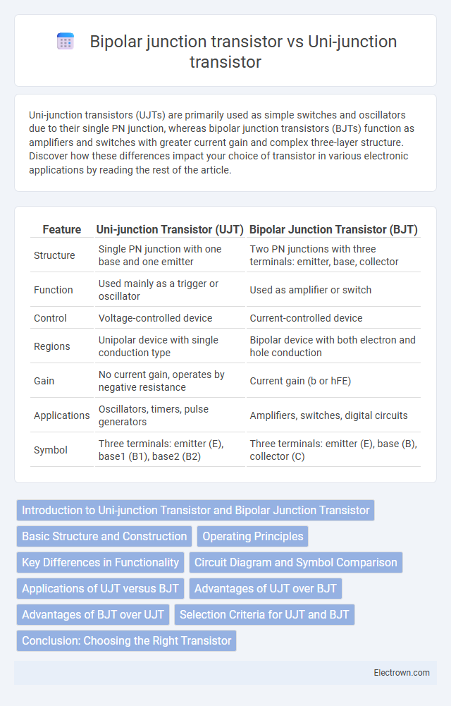
| Feature | Uni-junction Transistor (UJT) | Bipolar Junction Transistor (BJT) |
|---|---|---|
| Structure | Single PN junction with one base and one emitter | Two PN junctions with three terminals: emitter, base, collector |
| Function | Used mainly as a trigger or oscillator | Used as amplifier or switch |
| Control | Voltage-controlled device | Current-controlled device |
| Regions | Unipolar device with single conduction type | Bipolar device with both electron and hole conduction |
| Gain | No current gain, operates by negative resistance | Current gain (b or hFE) |
| Applications | Oscillators, timers, pulse generators | Amplifiers, switches, digital circuits |
| Symbol | Three terminals: emitter (E), base1 (B1), base2 (B2) | Three terminals: emitter (E), base (B), collector (C) |
Introduction to Uni-junction Transistor and Bipolar Junction Transistor
A Uni-junction transistor (UJT) is a three-terminal semiconductor device primarily used as a triggering device in oscillator circuits, characterized by its single PN junction and negative resistance region. In contrast, a Bipolar Junction Transistor (BJT) consists of three layers of alternating N and P-type semiconductors forming two PN junctions and is widely employed for amplification and switching applications. While UJTs operate mainly in the negative resistance region for pulse generation, BJTs function through current control, enabling high gain in electronic circuits.
Basic Structure and Construction
A Uni-junction transistor (UJT) consists of a single n-type semiconductor bar with a p-type region forming a single PN junction, resulting in three terminals: emitter, base1, and base2. In contrast, a Bipolar Junction Transistor (BJT) features two PN junctions arranged as either NPN or PNP layers, comprising three terminals: emitter, base, and collector. Understanding the basic structure helps you choose the right transistor based on switching speed, amplification, and triggering applications.
Operating Principles
Uni-junction transistors (UJTs) operate based on a single PN junction with a unique resistor-like characteristic that allows them to generate a sharp pulse when voltage at the emitter reaches a specific threshold. Bipolar junction transistors (BJTs) use two PN junctions in a sandwich structure (NPN or PNP) to amplify current by injecting minority carriers between the emitter and collector via the base. UJTs function primarily as triggering devices due to their negative resistance region, whereas BJTs serve as amplifiers or switches by controlling large collector currents with smaller base currents.
Key Differences in Functionality
Uni-junction transistors (UJTs) primarily function as switching devices and voltage triggers, utilizing a single pn junction to generate a negative resistance region for applications like oscillators and pulse generation. Bipolar junction transistors (BJTs) operate as current-controlled amplifiers with two pn junctions, allowing them to amplify or switch signals in analog and digital circuits. Your choice between UJT and BJT depends on whether you need a device for triggering and timing (UJT) or signal amplification and switching (BJT).
Circuit Diagram and Symbol Comparison
The Uni-junction transistor (UJT) circuit diagram features a single pn junction with three terminals: emitter, base 1 (B1), and base 2 (B2), while the Bipolar junction transistor (BJT) circuit diagram consists of two pn junctions forming either an NPN or PNP configuration with three terminals: emitter, base, and collector. The UJT symbol depicts a single junction with an arrow on the emitter terminal pointing toward or away from the base, indicating the direction of current flow, whereas the BJT symbol shows two junctions with an arrow on the emitter terminal indicating the type of transistor (NPN or PNP). Understanding these differences in circuit diagrams and symbols is crucial for correctly incorporating each transistor type into Your electronic designs.
Applications of UJT versus BJT
Uni-junction transistors (UJTs) are primarily used in timing circuits, pulse generation, and triggering applications such as in sawtooth oscillators and relaxation timers due to their ability to generate sharp pulses. Bipolar junction transistors (BJTs) are widely employed in amplification, switching, and signal processing across various electronic devices, including audio amplifiers, digital circuits, and power regulation systems. Your choice between UJT and BJT depends largely on whether you need pulse generation and triggering (UJT) or amplification and switching capabilities (BJT).
Advantages of UJT over BJT
Uni-junction transistors (UJT) offer advantages over bipolar junction transistors (BJT) such as simpler circuit design for triggering applications and higher efficiency in switching tasks thanks to their negative resistance region. UJT provides more reliable and precise control in timing and pulse generation circuits, making it ideal for oscillators and timers. Your choice of UJT can improve circuit stability and reduce complexity compared to BJT in specific triggering functions.
Advantages of BJT over UJT
Bipolar Junction Transistors (BJTs) offer higher current gain and better switching speed compared to Uni-Junction Transistors (UJTs), making them suitable for amplification and fast switching applications. BJTs provide greater input impedance, enhancing signal control in circuits requiring precise modulation. Their ability to operate effectively in both analog and digital circuits expands their versatility over the primarily triggering-focused UJTs.
Selection Criteria for UJT and BJT
Selection criteria for Uni-junction Transistors (UJT) prioritize applications requiring simple switching, relaxation oscillators, and triggering devices due to their negative resistance characteristic and ease of triggering at low voltages. Bipolar Junction Transistors (BJT) are chosen for amplification and high-speed switching applications, with considerations on current gain (hFE), voltage ratings, and power dissipation capacity. Device selection depends on required switching speed, control method (voltage-driven for UJT vs current-driven for BJT), and specific circuit function such as oscillator design or signal amplification.
Conclusion: Choosing the Right Transistor
Selecting between a Uni-junction transistor (UJT) and a Bipolar junction transistor (BJT) depends on the specific application requirements; UJTs excel in triggering circuits and pulse generation due to their negative resistance region, while BJTs provide robust amplification and switching capabilities with higher gain and faster response times. For high-frequency amplification and linear amplification tasks, BJTs are preferred because of their ability to handle larger currents and voltages efficiently. In contrast, UJTs are ideal for simple oscillators, timers, and waveform generators where precise control of triggering thresholds is critical.
Uni-junction transistor vs Bipolar junction transistor Infographic