Pseudo-NMOS logic offers faster switching speeds and reduced transistor count compared to CMOS logic, but it consumes static power due to the always-on pull-up transistor, impacting energy efficiency. Explore the article to understand how these differences affect your circuit design decisions.
Table of Comparison
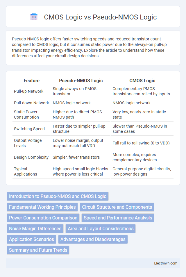
| Feature | Pseudo-NMOS Logic | CMOS Logic |
|---|---|---|
| Pull-up Network | Single always-on PMOS transistor | Complementary PMOS transistors controlled by inputs |
| Pull-down Network | NMOS logic network | NMOS logic network |
| Static Power Consumption | Higher due to direct PMOS-NMOS path | Very low, nearly zero in static state |
| Switching Speed | Faster due to simpler pull-up structure | Slower than Pseudo-NMOS in some cases |
| Output Voltage Levels | Lower noise margin, output may not reach full VDD | Full rail-to-rail swing (0 to VDD) |
| Design Complexity | Simpler, fewer transistors | More complex, requires complementary devices |
| Typical Applications | High-speed small logic blocks where power is less critical | General-purpose digital circuits, low-power designs |
Introduction to Pseudo-NMOS and CMOS Logic
Pseudo-NMOS logic employs a single nMOS transistor network with a constant pMOS transistor acting as a load, reducing transistor count and enhancing speed but increasing static power consumption. CMOS logic uses complementary pairs of pMOS and nMOS transistors to create low-power, robust digital circuits with full voltage swing and high noise margins. Your choice between Pseudo-NMOS and CMOS depends on power efficiency versus speed and transistor complexity requirements.
Fundamental Working Principles
Pseudo-NMOS logic uses a weak PMOS transistor as a load device constantly connected to the supply voltage, allowing the NMOS transistor to pull the output low during switching; this creates a simpler circuit with fewer transistors but consumes static power due to the always-on PMOS. CMOS logic employs complementary pairs of PMOS and NMOS transistors arranged so one transistor is always off during switching, resulting in low static power consumption and true rail-to-rail output voltages. The fundamental difference lies in the biasing of the pull-up device: Pseudo-NMOS uses a biased PMOS load, while CMOS uses fully complementary transistors that switch alternately.
Circuit Structure and Components
Pseudo-NMOS logic features a single NMOS transistor pull-down network paired with a constantly active PMOS transistor as a load, eliminating the need for a complementary PMOS pull-up network found in CMOS logic. CMOS logic consists of complementary pairs of NMOS and PMOS transistors that switch alternately, minimizing static power consumption and enhancing noise margins. Your choice between these structures impacts power efficiency, speed, and circuit complexity.
Power Consumption Comparison
Pseudo-NMOS logic consumes more static power than CMOS logic due to the always-on PMOS transistor, which causes continuous current flow when the output is low. In contrast, CMOS logic significantly reduces power consumption by ensuring only transient current flows during switching without static current draw. Your design choice impacts overall power efficiency, especially in low-power applications where CMOS logic is generally preferred.
Speed and Performance Analysis
Pseudo-NMOS logic offers faster switching speeds compared to traditional CMOS logic due to its simpler transistor arrangement, which reduces propagation delay by eliminating the pull-up PMOS transistor's switching time. However, this speed gain comes at the cost of higher static power consumption caused by the constant current flow through the always-on PMOS transistor in Pseudo-NMOS circuits. Your choice between Pseudo-NMOS and CMOS logic should balance the need for speed with power efficiency, as CMOS provides lower power consumption but generally slower operation.
Noise Margin Differences
Pseudo-NMOS logic exhibits lower noise margins compared to CMOS logic due to its static PMOS transistor always being on, which causes a weaker logic "0" level and increased susceptibility to noise. CMOS logic achieves higher noise margins by utilizing complementary pull-up and pull-down networks, ensuring full voltage swings from VDD to GND, thereby enhancing signal integrity. The reduced noise margins in pseudo-NMOS limit its reliability in low-voltage and high-speed applications, making CMOS the preferred choice for robust logic design.
Area and Layout Considerations
Pseudo-NMOS logic typically requires fewer transistors compared to CMOS logic, resulting in a smaller silicon area and simpler layout design. However, the always-on pull-up transistor in Pseudo-NMOS can lead to increased static power dissipation which influences layout thermal management. Your choice between Pseudo-NMOS and CMOS should consider the trade-off between area efficiency and power consumption in the specific application.
Application Scenarios
Pseudo-NMOS logic is commonly applied in high-speed, low-area integrated circuits where power consumption is less critical, making it suitable for small, performance-sensitive blocks like content-addressable memories and small multiplexers. CMOS logic dominates in low-power applications such as battery-operated devices, portable electronics, and large-scale digital systems due to its near-zero static power dissipation and scalability. The choice between Pseudo-NMOS and CMOS logic centers on balancing speed, power, and area constraints based on the specific application's requirements.
Advantages and Disadvantages
Pseudo-NMOS logic offers faster switching speeds and reduced transistor count compared to CMOS logic, making it suitable for high-speed applications with limited area. However, it consumes static power continuously due to a permanently-on pull-up transistor, resulting in higher power dissipation. In contrast, CMOS logic excels in low static power consumption and noise margins but generally has slower operation and larger transistor area requirements.
Summary and Future Trends
Pseudo-NMOS logic offers faster switching speeds and reduced area compared to CMOS but suffers from higher static power consumption due to the always-on pull-up transistor. CMOS logic remains the industry standard for low-power, high-noise-margin applications, benefiting from continuous advancements in device scaling and power-efficient architectures. Future trends indicate increased adoption of hybrid logic styles and novel materials to balance the speed advantages of Pseudo-NMOS with the energy efficiency of CMOS in emerging low-power and high-performance integrated circuits.
Pseudo-NMOS vs CMOS logic Infographic