The common emitter configuration provides high voltage gain and moderate current gain, making it ideal for amplifying signals with significant power output, while the common collector offers high current gain but unity voltage gain, primarily used for impedance matching and buffering. Explore the rest of the article to understand how these differences impact your circuit design choices.
Table of Comparison
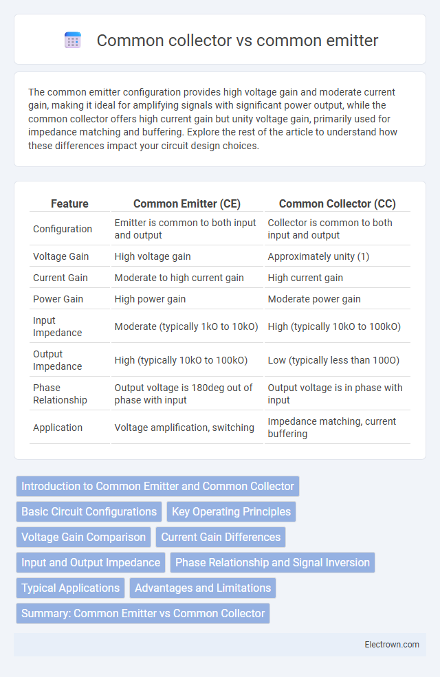
| Feature | Common Emitter (CE) | Common Collector (CC) |
|---|---|---|
| Configuration | Emitter is common to both input and output | Collector is common to both input and output |
| Voltage Gain | High voltage gain | Approximately unity (1) |
| Current Gain | Moderate to high current gain | High current gain |
| Power Gain | High power gain | Moderate power gain |
| Input Impedance | Moderate (typically 1kO to 10kO) | High (typically 10kO to 100kO) |
| Output Impedance | High (typically 10kO to 100kO) | Low (typically less than 100O) |
| Phase Relationship | Output voltage is 180deg out of phase with input | Output voltage is in phase with input |
| Application | Voltage amplification, switching | Impedance matching, current buffering |
Introduction to Common Emitter and Common Collector
Common emitter and common collector are fundamental bipolar junction transistor (BJT) configurations widely used in analog circuits. The common emitter configuration provides voltage gain and phase inversion, making it ideal for amplification purposes. In contrast, the common collector configuration, also known as an emitter follower, offers high input impedance and voltage buffering with unity gain, making it suitable for impedance matching.
Basic Circuit Configurations
The common emitter configuration features the emitter terminal as the common connection point for both input and output circuits, providing high voltage gain and moderate input impedance. In the common collector configuration, the collector terminal is common to both circuits, yielding high input impedance, low output impedance, and unity voltage gain, making it ideal for impedance matching. These distinct circuit topologies influence the transistor's amplification properties and signal handling in electronic applications.
Key Operating Principles
The common emitter configuration operates by using the emitter as a common terminal while the input signal is applied to the base and the output is taken from the collector, providing high voltage gain and phase inversion. In contrast, the common collector configuration, also known as the emitter follower, has the collector as the common terminal, with the input applied to the base and the output taken from the emitter, offering unity voltage gain and high current gain without phase inversion. Both configurations utilize the transistor's base-emitter junction for input control but differ fundamentally in their output characteristics and voltage-current amplification behavior.
Voltage Gain Comparison
The common emitter configuration provides a high voltage gain, often greater than one, making it ideal for amplification purposes. In contrast, the common collector configuration, also known as an emitter follower, offers a voltage gain close to unity, typically slightly less than one, with no significant voltage amplification. This distinction makes the common emitter suitable for voltage amplification stages while the common collector excels in impedance matching and buffering applications.
Current Gain Differences
Common emitter (CE) configurations provide a high current gain typically ranging from 100 to 300, making them ideal for amplification purposes where signal strength enhancement is crucial. Common collector (CC), also known as emitter follower, offers a current gain close to unity but delivers high input impedance and low output impedance, suitable for impedance matching rather than amplification. The CE's current gain depends on the transistor's beta, whereas in CC configurations, the current gain is approximately equal to (beta + 1), effectively ensuring near unity voltage gain but substantial current buffering.
Input and Output Impedance
The common emitter amplifier typically exhibits a moderate input impedance ranging from 1 kO to 10 kO and a high output impedance that can reach several kilo-ohms, making it suitable for voltage amplification applications. In contrast, the common collector amplifier, also known as an emitter follower, provides a high input impedance often exceeding 100 kO and a very low output impedance usually below 100 O, ideal for impedance matching and buffering tasks. These impedance characteristics directly influence circuit design choices regarding signal strength and load compatibility.
Phase Relationship and Signal Inversion
The common emitter amplifier produces a 180-degree phase shift between the input and output signals, resulting in signal inversion, whereas the common collector amplifier provides a phase relationship with no inversion, maintaining signal polarity. You can utilize the common emitter configuration for applications requiring signal amplification with phase reversal, while the common collector is ideal for impedance matching and buffering without altering phase. Understanding these phase relationships is crucial for designing circuits where signal integrity and phase alignment are critical.
Typical Applications
Common emitter configurations are widely used in amplification circuits due to their high voltage gain and moderate input and output impedance, making them ideal for audio amplifiers and signal processing. Common collector circuits, known as emitter followers, are preferred in impedance matching and buffering applications because of their high input impedance, low output impedance, and unity voltage gain. Both configurations serve essential roles in analog electronics, with common emitter amplifying signals and common collector providing stable voltage buffering.
Advantages and Limitations
Common emitter amplifiers provide high voltage gain and moderate input impedance, making them suitable for signal amplification but suffer from phase inversion and moderate bandwidth limitations. Common collector amplifiers, also known as emitter followers, offer high input impedance and low output impedance with unity voltage gain, ideal for impedance matching and buffering but do not provide voltage amplification. The choice between common emitter and common collector configurations depends on the specific requirements for gain, impedance, and phase characteristics in electronic circuit design.
Summary: Common Emitter vs Common Collector
Common emitter amplifiers provide high voltage and current gain, making them ideal for signal amplification in audio and radio frequency circuits. Common collector configurations, also known as emitter followers, offer unity voltage gain but high current gain, which is perfect for impedance matching and buffering applications. Understanding the differences in gain and impedance between these two transistor configurations helps you choose the best option for your electronic circuit design.
Common emitter vs common collector Infographic