Load-line analysis provides a graphical method to determine the operating point of a nonlinear device by plotting the device's characteristic curve against the load line, while small signal analysis focuses on linearizing the device behavior around the operating point to study its response to small input variations. Understanding both techniques will enhance your ability to analyze and design electronic circuits effectively; read on to explore their differences and practical applications.
Table of Comparison
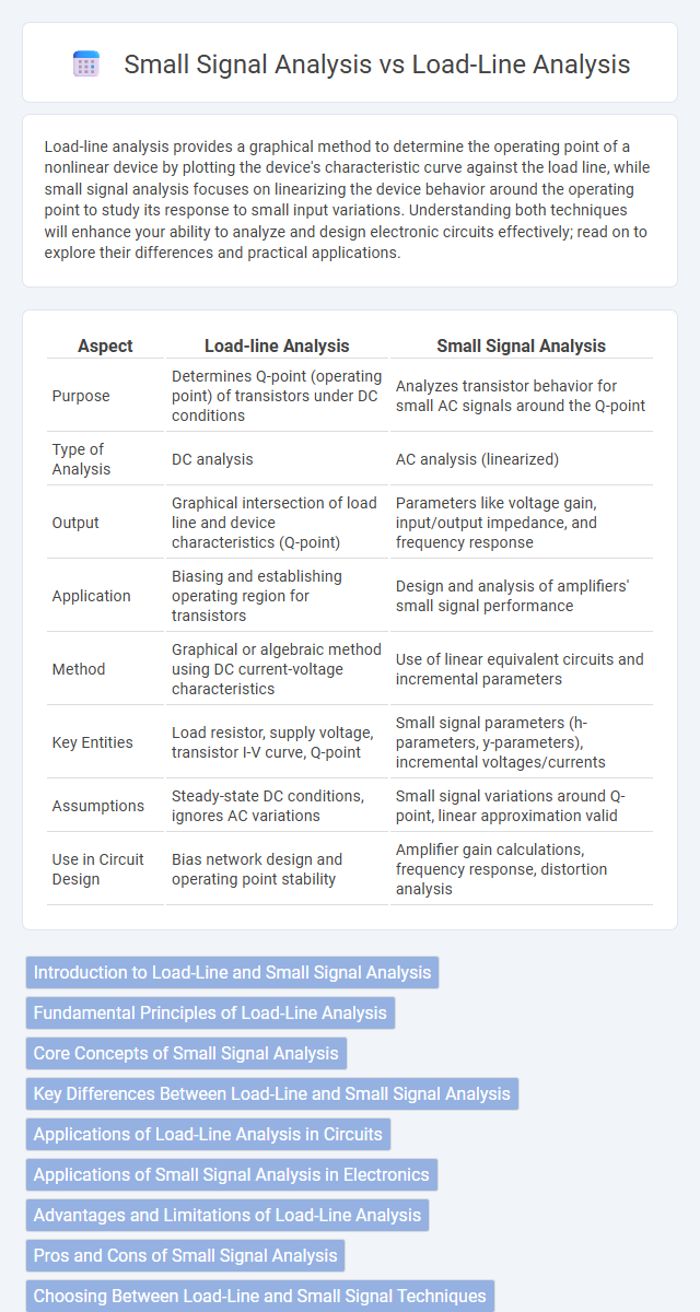
| Aspect | Load-line Analysis | Small Signal Analysis |
|---|---|---|
| Purpose | Determines Q-point (operating point) of transistors under DC conditions | Analyzes transistor behavior for small AC signals around the Q-point |
| Type of Analysis | DC analysis | AC analysis (linearized) |
| Output | Graphical intersection of load line and device characteristics (Q-point) | Parameters like voltage gain, input/output impedance, and frequency response |
| Application | Biasing and establishing operating region for transistors | Design and analysis of amplifiers' small signal performance |
| Method | Graphical or algebraic method using DC current-voltage characteristics | Use of linear equivalent circuits and incremental parameters |
| Key Entities | Load resistor, supply voltage, transistor I-V curve, Q-point | Small signal parameters (h-parameters, y-parameters), incremental voltages/currents |
| Assumptions | Steady-state DC conditions, ignores AC variations | Small signal variations around Q-point, linear approximation valid |
| Use in Circuit Design | Bias network design and operating point stability | Amplifier gain calculations, frequency response, distortion analysis |
Introduction to Load-Line and Small Signal Analysis
Load-line analysis graphically determines the operating point of nonlinear devices by intersecting device characteristic curves with circuit constraints, essential for designing amplifiers and biasing circuits. Small signal analysis examines the linearized behavior of electronic components around the operating point, enabling the calculation of parameters like voltage gain, input/output impedance, and frequency response. Both methods complement each other in amplifier design, with load-line analysis establishing bias conditions and small signal analysis predicting dynamic performance.
Fundamental Principles of Load-Line Analysis
Load-line analysis fundamentally represents the graphical intersection of device characteristics and circuit constraints to determine the operating point of nonlinear electronic components like transistors. This method involves plotting both the device's characteristic curve and the external circuit's load line to visualize current and voltage at equilibrium. Your understanding of load-line analysis enhances the ability to predict device behavior under various biasing conditions, distinguishing it from small signal analysis, which investigates incremental changes around this operating point.
Core Concepts of Small Signal Analysis
Small signal analysis focuses on linearizing a transistor's nonlinear behavior around its operating point by approximating the device with equivalent small-signal parameters like transconductance and output resistance. This method enables precise evaluation of the amplifier's incremental gain, input impedance, and output impedance under minor variations in the input signal. You can accurately predict the circuit's response to small input signals, which is crucial for designing stable and high-performance analog circuits.
Key Differences Between Load-Line and Small Signal Analysis
Load-line analysis focuses on the DC operation point of a transistor by graphically determining the intersection of the device characteristics with the external circuit constraints, helping to establish the Q-point for biasing. Small signal analysis, on the other hand, examines the transistor's response to small AC variations around this Q-point, enabling calculation of voltage gain, input, and output impedances. Your understanding of these key differences is critical for designing stable amplifiers and predicting both static and dynamic transistor behavior accurately.
Applications of Load-Line Analysis in Circuits
Load-line analysis is essential for determining the operating point (Q-point) in nonlinear circuits such as transistors and diodes, enabling designers to predict circuit behavior under DC conditions. It helps in biasing transistor amplifiers to ensure they operate within the desired active region, preventing cutoff or saturation. This technique is crucial in designing analog circuits, power amplifiers, and switching devices where accurate understanding of device characteristics is required for reliable performance.
Applications of Small Signal Analysis in Electronics
Small signal analysis is essential for designing and understanding the behavior of electronic amplifiers, oscillators, and filters under low-level input signals. It helps determine parameters like gain, input/output impedance, and frequency response, allowing precise optimization of circuit performance. You can use small signal techniques to predict how devices respond to small variations without altering their operating point, ensuring reliable and stable electronic system operation.
Advantages and Limitations of Load-Line Analysis
Load-line analysis offers a straightforward visual method to determine the operating point (Q-point) of nonlinear devices like transistors, providing quick insights into voltage and current behavior under static conditions. Its main advantage lies in simplicity and ease of application without requiring complex calculations, making it ideal for initial design and troubleshooting. However, load-line analysis is limited by its inability to account for dynamic changes or small-signal variations, which small signal analysis can accurately capture to predict AC response and gain in your circuits.
Pros and Cons of Small Signal Analysis
Small signal analysis offers precise insights into an electronic circuit's linear behavior by simplifying nonlinear components around their operating point, making it ideal for AC signal evaluation. Its limitation lies in its inability to accurately predict large signal or nonlinear behaviors, restricting its use to small variations and potentially overlooking distortion effects. The method excels in designing amplifiers and understanding frequency response but requires complementary techniques to fully characterize circuit performance under real-world signal conditions.
Choosing Between Load-Line and Small Signal Techniques
Choosing between load-line analysis and small signal analysis depends on the application and desired outcome. Load-line analysis is ideal for determining the operating point and large-signal behavior of transistors in power circuits, while small signal analysis excels at examining transistor response to minute input variations at the linear region. Your circuit design benefits from load-line analysis during biasing stages and from small signal analysis when refining gain, frequency response, or distortion in amplification tasks.
Summary: When to Use Each Analysis Method
Load-line analysis is ideal for determining the operating point of nonlinear devices like transistors under DC conditions, providing a graphical approach to visualize current and voltage interactions. Small signal analysis is best suited for examining the behavior of circuits in response to small input variations around the operating point, enabling linear approximation of dynamic performance such as gain and frequency response. Your choice depends on whether you need to analyze static operating conditions (use load-line) or dynamic signal variations (use small signal).
Load-line analysis vs small signal analysis Infographic