Ground loop noise occurs when multiple grounding paths create unwanted current flow, causing interference in audio and electrical systems. Understanding the difference between ground loop and common mode noise can improve Your system's performance; continue reading to learn how to effectively manage these issues.
Table of Comparison
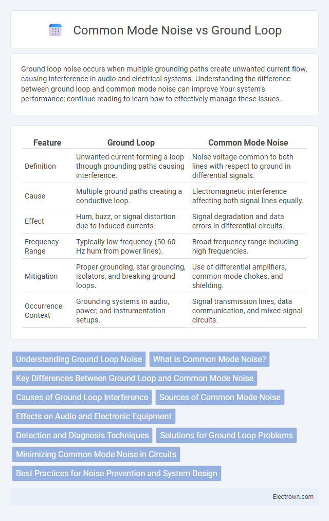
| Feature | Ground Loop | Common Mode Noise |
|---|---|---|
| Definition | Unwanted current forming a loop through grounding paths causing interference. | Noise voltage common to both lines with respect to ground in differential signals. |
| Cause | Multiple ground paths creating a conductive loop. | Electromagnetic interference affecting both signal lines equally. |
| Effect | Hum, buzz, or signal distortion due to induced currents. | Signal degradation and data errors in differential circuits. |
| Frequency Range | Typically low frequency (50-60 Hz hum from power lines). | Broad frequency range including high frequencies. |
| Mitigation | Proper grounding, star grounding, isolators, and breaking ground loops. | Use of differential amplifiers, common mode chokes, and shielding. |
| Occurrence Context | Grounding systems in audio, power, and instrumentation setups. | Signal transmission lines, data communication, and mixed-signal circuits. |
Understanding Ground Loop Noise
Ground loop noise occurs when multiple grounding paths create a voltage differential, causing unwanted current to flow and introduce interference in audio and electronic systems. This noise often manifests as a hum or buzz, particularly in systems with interconnected equipment sharing different ground potentials. Proper grounding techniques and isolation methods are essential to eliminate ground loop noise and ensure signal integrity.
What is Common Mode Noise?
Common Mode Noise refers to unwanted electrical interference that appears equally on two or more signal lines relative to a common ground, often caused by electromagnetic interference or power supply fluctuations. It affects the integrity of your data transmission by introducing noise signals that are identical in phase and amplitude on all affected conductors. Understanding Common Mode Noise is crucial for designing effective grounding and shielding solutions to minimize signal degradation and enhance system performance.
Key Differences Between Ground Loop and Common Mode Noise
Ground loop noise occurs due to voltage differences between multiple grounding points, creating unwanted current loops that interfere with signal integrity. Common mode noise arises when identical unwanted signals are coupled onto both lines of a differential pair, typically from external electromagnetic interference. The key difference lies in the source; ground loop noise is caused by grounding issues, while common mode noise results from external interference affecting both conductors simultaneously.
Causes of Ground Loop Interference
Ground loop interference is primarily caused by multiple grounding paths creating a voltage difference between connected equipment, leading to unwanted current flow. Differences in ground potential arise from improper grounding practices, long cable runs, or connecting devices powered from different electrical sources. Your audio and video systems can experience hum, buzzing, or signal degradation due to these ground loop currents, making proper grounding essential to minimize interference.
Sources of Common Mode Noise
Common mode noise originates from electromagnetic interference induced in signal cables, power lines, and grounding systems caused by nearby electrical equipment, fluorescent lighting, and radio frequency sources. Ground loops create a voltage difference between interconnected equipment grounds, exacerbating common mode noise by allowing unwanted current flow through the grounding path. Understanding the specific sources such as HVAC systems, motors, and switching power supplies is crucial to effectively minimize common mode noise in sensitive electronic applications.
Effects on Audio and Electronic Equipment
Ground loop noise creates low-frequency hums that degrade audio quality, causing unwanted vibrations and interference in audio equipment. Common mode noise introduces high-frequency interference that disrupts electronic circuits, leading to signal distortion and reduced performance in sensitive devices. Protecting your audio and electronic equipment from these noises ensures clearer sound reproduction and more reliable operation.
Detection and Diagnosis Techniques
Ground loop noise and common mode noise are primarily detected using oscilloscopes and spectrum analyzers to capture differential and common mode signals in electrical circuits. Techniques such as using isolation transformers, differential probes, and current clamps help diagnose ground loops by identifying unintended current paths and voltage differences between ground points. For common mode noise, vector network analyzers and impedance analyzers measure the noise coupling and propagation, enabling targeted filtering and mitigation strategies.
Solutions for Ground Loop Problems
Ground loop problems can be resolved by isolating the ground paths using isolation transformers or differential amplifiers to break the loop and prevent unwanted current flow. Implementing proper grounding techniques such as a single-point ground system significantly reduces differences in ground potential, thereby minimizing noise pickup. Using shielded cables and balanced line transmission also mitigates common mode noise, improving overall signal integrity in sensitive electronic systems.
Minimizing Common Mode Noise in Circuits
Minimizing common mode noise in circuits involves implementing proper grounding techniques such as using a single-point ground to prevent ground loop formation and reduce noise interference. Employing differential signaling and balanced transmission lines enhances noise rejection by ensuring that noise affects both lines equally and is canceled out. Shielding cables with grounded conductive layers and using common mode chokes further suppress electromagnetic interference and improve overall signal integrity.
Best Practices for Noise Prevention and System Design
Ground loop and common mode noise can severely affect signal integrity in electronic systems, so implementing best practices like proper grounding techniques, using isolation transformers, and minimizing ground loop areas is crucial. Designing your system with twisted pair cables, differential signaling, and careful PCB layout reduces susceptibility to noise interference. Ensuring that all components share a single reference ground point helps prevent potential differences that cause ground loop currents and common mode noise.
Ground Loop vs Common Mode Noise Infographic