Open collector outputs allow multiple devices to share a line by only pulling it low, requiring an external pull-up resistor to define the high state, while push-pull outputs actively drive the line both high and low for faster switching and stronger signal integrity. Understanding these differences can optimize your circuit design, so continue reading to explore the detailed comparisons and applications.
Table of Comparison
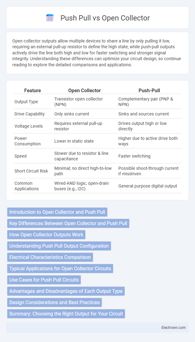
| Feature | Open Collector | Push-Pull |
|---|---|---|
| Output Type | Transistor open collector (NPN) | Complementary pair (PNP & NPN) |
| Drive Capability | Only sinks current | Sinks and sources current |
| Voltage Levels | Requires external pull-up resistor | Drives output high or low directly |
| Power Consumption | Lower in static state | Higher due to active drive both ways |
| Speed | Slower due to resistor & line capacitance | Faster switching |
| Short Circuit Risk | Minimal; no direct high-to-low path | Possible shoot-through current if misdriven |
| Common Applications | Wired-AND logic, open-drain buses (e.g., I2C) | General purpose digital output |
Introduction to Open Collector and Push Pull
Open Collector and Push Pull are two common output configurations used in digital electronics for driving loads and interfacing with other circuits. Open Collector outputs rely on a transistor that sinks current, requiring an external pull-up resistor to provide a high logic level, enabling wired-AND connections and level shifting. Push Pull outputs actively drive both high and low states using complementary transistors, offering faster switching speeds and better signal integrity for direct interfacing with your digital circuits.
Key Differences Between Open Collector and Push Pull
Open Collector outputs rely on a transistor that sinks current to ground, requiring an external pull-up resistor to define the output voltage level, while Push Pull outputs actively drive both high and low states with internal transistors. Open Collector designs are ideal for wired-AND logic and interfacing with different voltage levels, whereas Push Pull configurations offer faster switching speeds and stronger drive capabilities for standard digital signals. Your choice depends on application needs such as power consumption, speed, and the requirement for multi-device communication on a shared bus.
How Open Collector Outputs Work
Open Collector outputs work by using a transistor to connect the output to ground, allowing external components like pull-up resistors to define the high voltage level. This design enables multiple Open Collector outputs to be wired together in a wired-AND configuration, facilitating easy communication between multiple devices. Your circuit benefits from increased flexibility and noise immunity when using Open Collector outputs compared to Push Pull configurations.
Understanding Push Pull Output Configuration
Push-pull output configuration actively drives the output both high and low, providing fast switching speed and low output impedance, ideal for driving loads directly. Unlike open collector outputs that require an external pull-up resistor and can only sink current, push-pull outputs can source and sink current, ensuring better signal integrity and stronger voltage levels. Understanding this configuration helps you choose the right output type for applications demanding high-speed digital signals and efficient power usage.
Electrical Characteristics Comparison
Open collector outputs operate by sinking current to ground, requiring an external pull-up resistor to define the output voltage level, which results in slower rise times due to resistor-capacitance charging. Push-pull outputs actively drive the output high and low using complementary transistors, providing faster switching speeds and stronger drive capability with lower output impedance. The open collector configuration offers flexibility for wired-AND logic and level shifting, while push-pull circuits deliver better noise immunity and power efficiency in driving loads.
Typical Applications for Open Collector Circuits
Open collector circuits are commonly used in applications such as digital communication interfaces, LED driving, and relay control where wired-AND logic or level shifting is required. These circuits enable multiple outputs to be connected to a single line without causing damage, making them ideal for bus systems like I2C and interrupt signaling. Their ability to interface with different voltage levels and provide open-drain outputs makes them suitable for mixed-voltage environments.
Use Cases for Push Pull Circuits
Push-pull circuits are ideal for applications requiring high-speed switching and efficient power delivery, such as driving LEDs, motors, and digital logic signals. They provide both sourcing and sinking current capabilities, making them suitable for output stages in microcontrollers and communication interfaces. Your projects benefit from their ability to minimize voltage drop and improve signal integrity in demanding environments.
Advantages and Disadvantages of Each Output Type
Open Collector outputs provide flexible wired-AND logic and easy level shifting, making them ideal for interfacing with different voltage levels, but they require an external pull-up resistor and can be slower due to transistor saturation. Push-Pull outputs offer faster switching speeds and stronger drive capabilities by actively driving both high and low states, eliminating the need for pull-up resistors, but they lack the ability to share lines easily and can cause bus contention if multiple outputs drive the same line simultaneously. Choosing between the two depends on application requirements such as speed, noise immunity, and bus configuration.
Design Considerations and Best Practices
Open collector outputs require external pull-up resistors, allowing multiple devices to share a single line for wired-AND logic and preventing bus contention in mixed-voltage systems. Push-pull outputs offer stronger drive capability with actively driven high and low states, making them ideal for fast switching and precise signal control. Best practices include choosing open collector for diode-OR configurations and open-drain compatibility, while push-pull suits applications needing low output impedance and faster rise/fall times.
Summary: Choosing the Right Output for Your Circuit
Open Collector outputs provide flexibility by allowing multiple devices to share a common line for wired-AND logic and are ideal for interfacing with different voltage levels, while Push Pull outputs actively drive both high and low states, offering faster switching speeds and stronger signal integrity. Your choice depends on application needs: Open Collector suits scenarios requiring bus sharing or level shifting, whereas Push Pull is preferable for high-speed, low-noise digital signals. Evaluating factors like load type, voltage compatibility, and switching speed ensures optimal circuit performance with the appropriate output configuration.
Open Collector vs Push Pull Infographic