JK Flip-Flops eliminate invalid states found in SR Flip-Flops by allowing toggling behavior when both inputs are high, offering more flexibility in digital circuits. Discover how JK Flip-Flops compare to simpler D Flip-Flops and which type best suits your application's needs by reading the full article.
Table of Comparison
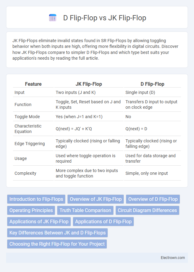
| Feature | JK Flip-Flop | D Flip-Flop |
|---|---|---|
| Input | Two inputs (J and K) | Single input (D) |
| Function | Toggle, Set, Reset based on J and K inputs | Transfers D input to output on clock edge |
| Toggle Mode | Yes (when J=1 and K=1) | No |
| Characteristic Equation | Q(next) = JQ' + K'Q | Q(next) = D |
| Edge Triggering | Typically clocked (rising or falling edge) | Typically clocked (rising or falling edge) |
| Usage | Used where toggle operation is required | Used for data storage and transfer |
| Complexity | More complex due to two inputs and toggle function | Simple, only one input |
Introduction to Flip-Flops
Flip-flops are fundamental memory elements in digital electronics used to store binary information. A JK Flip-Flop overcomes the limitations of the SR Flip-Flop by eliminating illegal states through its toggle functionality, while a D Flip-Flop simplifies data storage by capturing the input value on a clock edge. Your choice between JK and D Flip-Flops depends on the required operation, with JK offering versatility and D providing straightforward data latching.
Overview of JK Flip-Flop
JK Flip-Flop is a versatile bistable multivibrator used in digital circuits for storing binary information, capable of toggling its output based on inputs J (set) and K (reset). Unlike the D Flip-Flop, the JK Flip-Flop eliminates the invalid state by functioning as a universal flip-flop, allowing you to implement various logic functions such as memory storage, counters, and shift registers. Its characteristic table and excitation table provide optimized control over output state transitions, making it essential for sequential logic design.
Overview of D Flip-Flop
The D Flip-Flop is a fundamental memory element in digital circuits designed to store a single bit of data. It captures the input value (D) on the triggering edge of the clock signal, ensuring synchronized data storage and preventing glitches. Widely used in shift registers, counters, and memory devices, the D Flip-Flop simplifies design by eliminating the undefined states present in JK Flip-Flops.
Operating Principles
JK Flip-Flops operate based on toggling, setting, or resetting states according to the inputs J and K, with the ability to handle the ambiguous state that arises in SR flip-flops. D Flip-Flops capture the input value D at a specific clock edge, providing a straightforward and predictable one-bit memory storage. Your choice between JK and D Flip-Flops depends on whether you need versatile toggling functionality or simple data storage with minimal setup.
Truth Table Comparison
The JK Flip-Flop truth table features inputs J and K controlling the output, with states that toggle, reset, or set depending on the input combination, while the D Flip-Flop has a straightforward truth table where the output directly follows the input D at the clock edge. The JK Flip-Flop's characteristic toggling behavior allows it to overcome the indeterminate state present in the SR Flip-Flop, providing more versatile control in sequential circuits. Your choice between JK and D Flip-Flops should consider whether you need simple data storage (D Flip-Flop) or more complex toggling and control capabilities (JK Flip-Flop) based on their truth tables.
Circuit Diagram Differences
The JK Flip-Flop circuit includes two inputs, J and K, with feedback loops that prevent invalid states, whereas the D Flip-Flop features a single data input (D) that directly controls the output, ensuring simpler operation. JK Flip-Flops require additional logic gates such as AND and NOR gates to handle toggling states, while D Flip-Flops use a straightforward setup with a single latch or master-slave configuration. The circuit diagram of the JK Flip-Flop appears more complex due to its feedback and gating mechanisms, contrasting with the simpler, more linear design of the D Flip-Flop diagram.
Applications of JK Flip-Flop
JK Flip-Flops find extensive applications in digital electronics for implementing counters, shift registers, and frequency dividers due to their toggle capability when both inputs are high. They are widely used in building sequential circuits such as memory storage elements, toggle flip-flop circuits, and pulse detection systems. Their versatility in handling race conditions makes them ideal for designing control logic in synchronous systems.
Applications of D Flip-Flop
D Flip-Flops are widely used in digital circuits for data storage, synchronization, and edge-triggered data transfer, making them essential in shift registers, counters, and memory devices. Their ability to store a single bit of data and transfer it on the clock edge ensures precise timing control in sequential logic designs. Your digital system benefits from D Flip-Flops' simplicity and reliability in creating stable, clocked storage elements.
Key Differences Between JK and D Flip-Flops
JK flip-flops feature two inputs, J and K, allowing toggling behavior when both inputs are high, unlike D flip-flops which have a single data input that directly sets the output state. The JK flip-flop offers more flexibility by eliminating invalid states present in simpler SR flip-flops, making it ideal for toggling and counting applications. D flip-flops ensure data stability by sampling the input only on clock edges, minimizing glitches and providing straightforward data storage in synchronous circuits.
Choosing the Right Flip-Flop for Your Project
Selecting the appropriate flip-flop depends on the specific requirements of your digital circuit, such as the need for toggle behavior or simple data storage. JK Flip-Flops offer versatility with their ability to toggle outputs based on input combinations, making them ideal for counters and frequency dividers. D Flip-Flops provide straightforward data storage with a single data input, which simplifies timing control in registers and memory devices.
JK Flip-Flop vs D Flip-Flop Infographic