CMOS inverters offer lower power consumption and higher noise immunity compared to TTL inverters, which are known for faster switching speeds but higher power dissipation. Understanding these differences can help you choose the right inverter technology for your electronic design needs; read on to explore detailed comparisons and applications.
Table of Comparison
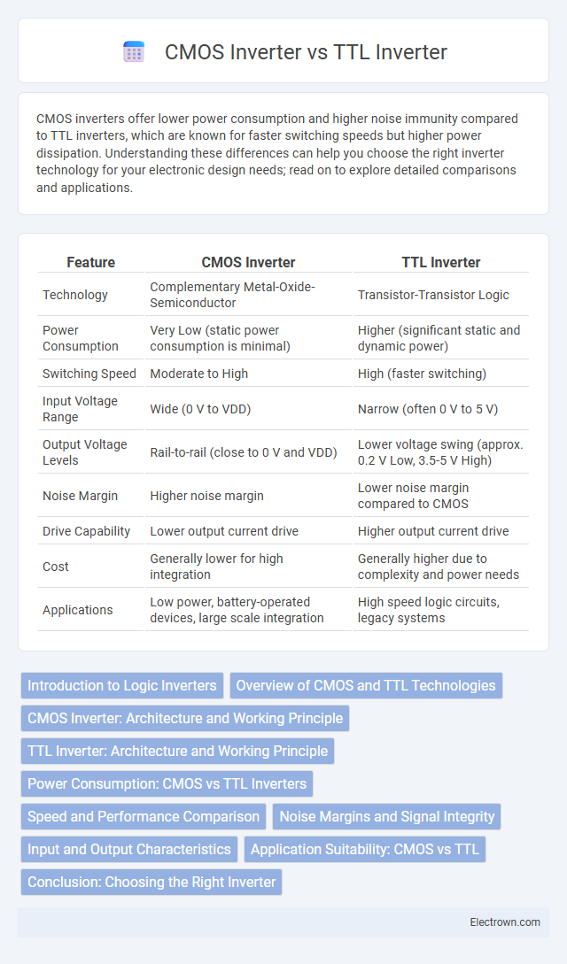
| Feature | CMOS Inverter | TTL Inverter |
|---|---|---|
| Technology | Complementary Metal-Oxide-Semiconductor | Transistor-Transistor Logic |
| Power Consumption | Very Low (static power consumption is minimal) | Higher (significant static and dynamic power) |
| Switching Speed | Moderate to High | High (faster switching) |
| Input Voltage Range | Wide (0 V to VDD) | Narrow (often 0 V to 5 V) |
| Output Voltage Levels | Rail-to-rail (close to 0 V and VDD) | Lower voltage swing (approx. 0.2 V Low, 3.5-5 V High) |
| Noise Margin | Higher noise margin | Lower noise margin compared to CMOS |
| Drive Capability | Lower output current drive | Higher output current drive |
| Cost | Generally lower for high integration | Generally higher due to complexity and power needs |
| Applications | Low power, battery-operated devices, large scale integration | High speed logic circuits, legacy systems |
Introduction to Logic Inverters
CMOS inverters operate using complementary pairs of p-type and n-type MOSFETs, providing high noise margins and low power consumption due to negligible static current flow. TTL inverters utilize bipolar junction transistors, offering faster switching speeds but higher power dissipation compared to CMOS technology. The differences in device structure lead to varying characteristics in input impedance, output drive capability, and overall efficiency in digital logic circuits.
Overview of CMOS and TTL Technologies
CMOS inverters use complementary pairs of p-type and n-type MOSFETs, offering high noise immunity and low power consumption, making them ideal for battery-powered devices. TTL inverters rely on bipolar junction transistors (BJTs) that provide faster switching speeds but consume more power, suitable for high-speed applications. Your choice between CMOS and TTL inverters depends on trade-offs in speed, power efficiency, and integration complexity.
CMOS Inverter: Architecture and Working Principle
The CMOS inverter consists of complementary MOSFETs--an n-channel and a p-channel transistor--connected in series between the power supply and ground, with their gates tied together as the input and the output taken from the connection between the two transistors. When the input voltage is low, the p-channel MOSFET is on and the n-channel MOSFET is off, pulling the output high; conversely, when the input voltage is high, the n-channel MOSFET conducts and the p-channel MOSFET is off, driving the output low. This complementary switching characteristic enables minimal static power dissipation and high noise immunity, making CMOS inverters highly efficient compared to TTL inverters.
TTL Inverter: Architecture and Working Principle
TTL inverter architecture relies on bipolar junction transistors arranged in multi-emitter input configurations to switch the output between high and low states. The working principle involves input signals controlling transistor conduction paths, causing saturation or cutoff states that determine output voltage levels. This design offers faster switching speeds due to low input impedance and direct transistor current steering compared to CMOS inverters.
Power Consumption: CMOS vs TTL Inverters
CMOS inverters exhibit significantly lower power consumption compared to TTL inverters due to their high input impedance and minimal static current flow when in a steady state. TTL inverters draw continuous current even when output is static, resulting in higher power dissipation and heat generation. Understanding these differences helps optimize Your circuit's energy efficiency and thermal management, especially in battery-powered or compact electronic devices.
Speed and Performance Comparison
CMOS inverters generally offer lower power consumption but slower switching speeds compared to TTL inverters, which achieve higher speed operation due to transistor-transistor logic design. Your choice between CMOS and TTL inverters depends on performance requirements, as TTL inverters typically provide faster switching times, making them suitable for high-speed applications. CMOS technology continues to improve, narrowing the speed gap while maintaining superior energy efficiency.
Noise Margins and Signal Integrity
CMOS inverters exhibit higher noise margins, typically around 30-40% of the supply voltage, enhancing their robustness against voltage fluctuations and ensuring superior signal integrity. TTL inverters have comparatively lower noise margins, generally near 10-20%, making them more susceptible to noise and signal degradation. The superior noise immunity of CMOS technology minimizes signal distortion and crosstalk, resulting in more reliable digital circuit operation under varied electrical conditions.
Input and Output Characteristics
CMOS inverters exhibit high input impedance, resulting in minimal input current and reduced power consumption, while TTL inverters have lower input impedance, leading to higher input current and increased power usage. CMOS output stages drive both high and low logic levels symmetrically with rail-to-rail voltage swing, offering a full voltage output range; TTL outputs typically saturate and have asymmetric output voltage levels, with a stronger ability to sink current than to source it. The input threshold voltage of CMOS inverters is approximately half the supply voltage, ensuring noise margin symmetry, whereas TTL inverters present a fixed threshold voltage around 0.8 V, influencing switching behavior and noise immunity.
Application Suitability: CMOS vs TTL
CMOS inverters excel in low-power, high-density applications such as battery-powered devices and integrated circuits due to their minimal static power consumption and high noise immunity. TTL inverters are preferred in high-speed switching and environments requiring robust performance with higher noise margins, commonly found in industrial control and legacy systems. The choice between CMOS and TTL inverters depends on balancing power efficiency, switching speed, and operational environment requirements.
Conclusion: Choosing the Right Inverter
CMOS inverters offer lower power consumption and higher noise immunity compared to TTL inverters, making them ideal for battery-powered and high-density integrated circuits. TTL inverters provide faster switching speeds and better fan-out capabilities, suitable for applications requiring high-speed digital logic. Your choice depends on balancing power efficiency with speed demands, where CMOS is preferred for low power and TTL for performance-critical tasks.
CMOS inverter vs TTL inverter Infographic