ICD (In-Circuit Debugger) allows real-time debugging of microcontrollers by interfacing directly with the target device's pins, enabling you to monitor and control execution without removing the chip from the circuit. JTAG (Joint Test Action Group) is a standardized interface primarily used for testing and programming, providing access to internal registers and memory for diagnostics and boundary scan testing; explore the rest of this article to understand their differences and applications fully.
Table of Comparison
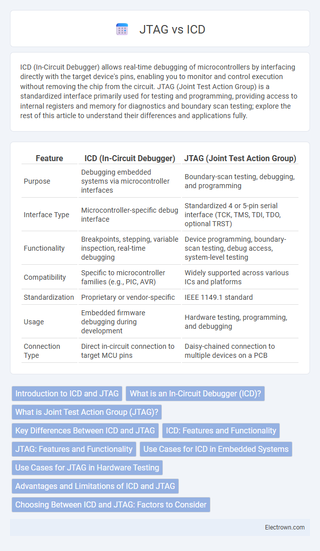
| Feature | ICD (In-Circuit Debugger) | JTAG (Joint Test Action Group) |
|---|---|---|
| Purpose | Debugging embedded systems via microcontroller interfaces | Boundary-scan testing, debugging, and programming |
| Interface Type | Microcontroller-specific debug interface | Standardized 4 or 5-pin serial interface (TCK, TMS, TDI, TDO, optional TRST) |
| Functionality | Breakpoints, stepping, variable inspection, real-time debugging | Device programming, boundary-scan testing, debug access, system-level testing |
| Compatibility | Specific to microcontroller families (e.g., PIC, AVR) | Widely supported across various ICs and platforms |
| Standardization | Proprietary or vendor-specific | IEEE 1149.1 standard |
| Usage | Embedded firmware debugging during development | Hardware testing, programming, and debugging |
| Connection Type | Direct in-circuit connection to target MCU pins | Daisy-chained connection to multiple devices on a PCB |
Introduction to ICD and JTAG
ICD (In-Circuit Debugger) and JTAG (Joint Test Action Group) are essential tools for embedded system development and debugging. ICD allows developers to debug microcontrollers directly within the circuit, offering real-time control and monitoring of code execution. JTAG serves as a standardized interface for testing, programming, and debugging integrated circuits, enabling boundary-scan testing and access to internal device registers.
What is an In-Circuit Debugger (ICD)?
An In-Circuit Debugger (ICD) is a hardware tool that allows you to test and debug embedded systems by interfacing directly with the microcontroller or processor while the system is running. It provides real-time control and visibility into the internal operations of the device, enabling breakpoints, step execution, and memory inspection. Compared to JTAG, which is primarily a standard interface for boundary scan testing and device programming, an ICD offers a broader range of debugging capabilities within live circuits.
What is Joint Test Action Group (JTAG)?
Joint Test Action Group (JTAG) is an industry standard for verifying designs and testing printed circuit boards after manufacture using boundary scan architecture. It provides a method for accessing and controlling individual pins on integrated circuits, enabling debugging, programming, and testing without physical probes. Understanding JTAG can enhance your ability to perform in-depth chip-level diagnostics and system validation efficiently.
Key Differences Between ICD and JTAG
ICD (In-Circuit Debugger) uses a dedicated microcontroller interface for real-time debugging and programming, while JTAG (Joint Test Action Group) operates via a standardized boundary-scan interface primarily for testing and debugging integrated circuits. ICD provides direct control over the microcontroller's internal registers and memory, enabling precise debugging during development. JTAG supports multiple devices in a chain and is widely used for device programming, boundary-scan testing, and system-level diagnostics, giving your projects enhanced flexibility and scalability.
ICD: Features and Functionality
In-Circuit Debugger (ICD) offers real-time debugging capabilities by allowing direct access to the microcontroller's internal state without removing it from the circuit, enabling efficient code testing and fault diagnosis. Key features include breakpoints, single-stepping, watch windows, and memory inspection, which facilitate thorough debugging during development. ICD supports seamless integration with development environments, enhancing productivity by providing immediate feedback and precise control over embedded systems.
JTAG: Features and Functionality
JTAG (Joint Test Action Group) provides advanced debugging and testing capabilities by enabling boundary-scan testing, in-system programming, and real-time device control through a standardized interface. Its key features include allowing direct access to internal registers, facilitating device verification, and supporting multi-chip systems for comprehensive diagnostic procedures. When using JTAG, your development process benefits from streamlined hardware testing and efficient fault isolation, improving overall product reliability.
Use Cases for ICD in Embedded Systems
ICD (In-Circuit Debugger) is essential in embedded systems for real-time debugging, enabling developers to pause execution, inspect memory, and modify code directly on the microcontroller. It supports fault diagnosis and performance optimization during firmware development, facilitating step-by-step code execution to identify issues effectively. ICD is particularly advantageous for complex embedded applications requiring precise control and immediate feedback without removing the chip from the circuit.
Use Cases for JTAG in Hardware Testing
JTAG (Joint Test Action Group) is extensively used for boundary-scan testing, allowing direct access to individual pins on integrated circuits to detect faults like shorts and opens without physical probes. It facilitates in-system programming and debugging of microcontrollers and FPGAs, enabling developers to test and program devices after manufacturing and during development. JTAG's use in hardware testing enhances fault isolation, improves production yield, and streamlines the validation of complex multi-chip electronic systems.
Advantages and Limitations of ICD and JTAG
In-circuit debugging (ICD) offers the advantage of direct control and real-time observation of the microcontroller's internal operations without removing it from the circuit, making it ideal for software development and fault diagnosis. JTAG (Joint Test Action Group) provides extensive boundary-scan testing capabilities, enabling detection of manufacturing defects and facilitating programming of multiple devices in complex hardware setups. Limitations of ICD include dependency on the target device's probe availability and limited support for non-debuggable chips, whereas JTAG's complexity and slower data transfer rates may restrict its efficiency in real-time debugging scenarios.
Choosing Between ICD and JTAG: Factors to Consider
When choosing between ICD and JTAG for debugging and programming microcontrollers, consider factors such as device compatibility, communication speed, and feature support. ICD (In-Circuit Debugger) is often preferred for simpler applications with limited pins, while JTAG provides more comprehensive testing and access to advanced debug features ideal for complex systems. Your development environment and specific project requirements will determine the most effective interface to streamline debugging and improve efficiency.
ICD vs JTAG Infographic