Ripple rejection measures how well an electronic device suppresses periodic variations in its power supply voltage, while common mode rejection evaluates the device's ability to eliminate interference signals that are common to both input lines. Understanding the difference between ripple rejection and common mode rejection can enhance your grasp of signal integrity and noise reduction; explore the rest of the article to dive deeper into these critical concepts.
Table of Comparison
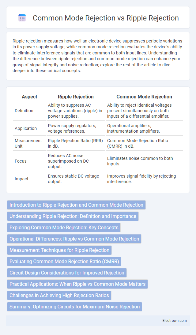
| Aspect | Ripple Rejection | Common Mode Rejection |
|---|---|---|
| Definition | Ability to suppress AC voltage variations (ripple) in power supplies. | Ability to reject identical voltages present simultaneously on both inputs of a differential amplifier. |
| Application | Power supply regulators, voltage references. | Operational amplifiers, instrumentation amplifiers. |
| Measurement Unit | Ripple Rejection Ratio (RRR) in dB. | Common Mode Rejection Ratio (CMRR) in dB. |
| Focus | Reduces AC noise superimposed on DC output. | Eliminates noise common to both inputs. |
| Impact | Ensures stable DC voltage output. | Improves signal fidelity by rejecting interference. |
Introduction to Ripple Rejection and Common Mode Rejection
Ripple rejection measures an amplifier's ability to minimize the impact of power supply voltage fluctuations on the output signal, enhancing signal stability. Common mode rejection quantifies how effectively an amplifier can suppress unwanted signals present simultaneously on both input lines, crucial for reducing noise in differential circuits. Understanding these parameters helps improve Your system's signal integrity and performance in noisy electrical environments.
Understanding Ripple Rejection: Definition and Importance
Ripple rejection measures an amplifier's ability to suppress voltage fluctuations caused by power supply noise, ensuring signal integrity in sensitive electronic circuits. High ripple rejection is crucial for maintaining low distortion and stable operation in audio, communication, and precision measurement systems. This parameter differs from common mode rejection, which targets noise signals appearing equally on both input lines, emphasizing the unique role ripple rejection plays in filtering power supply interference.
Exploring Common Mode Rejection: Key Concepts
Common Mode Rejection (CMR) measures a system's ability to reject input signals common to both input leads, critical in minimizing noise and interference in differential amplifiers. High CMR ratios enhance signal integrity by suppressing unwanted noise present equally on both inputs, often quantified in decibels (dB). Ripple rejection, by contrast, specifically addresses an amplifier's capacity to reduce ripple voltages from power supplies, making CMR a broader and more essential parameter in precision analog circuit design.
Operational Differences: Ripple vs Common Mode Rejection
Ripple rejection primarily addresses the ability of a circuit or device to suppress unwanted AC variations or fluctuations (ripple) in the power supply voltage, ensuring steady DC output. Common mode rejection, on the other hand, refers to the device's capacity to minimize interference or noise signals that appear simultaneously and in-phase on both input lines, improving signal integrity in differential amplifiers. Understanding the operational differences between ripple rejection and common mode rejection helps you select the appropriate noise filtering method for your specific electronic applications.
Measurement Techniques for Ripple Rejection
Measuring ripple rejection involves applying a controlled AC ripple voltage to the power supply input and monitoring the amplifier's output to quantify the attenuation of these variations. Common mode rejection is assessed by simultaneously applying identical noise signals to both inputs of a differential amplifier and measuring the output response to evaluate the circuit's ability to reject interference. Precision instruments like network analyzers and spectrum analyzers are commonly used to capture these metrics with high accuracy in both ripple and common mode rejection tests.
Evaluating Common Mode Rejection Ratio (CMRR)
Common Mode Rejection Ratio (CMRR) measures an amplifier's ability to reject input signals common to both input leads, essential for minimizing the effect of noise and interference in differential amplifiers. A high CMRR value indicates superior performance in isolating the desired differential signal from common mode voltage, improving signal integrity in your systems. Evaluating CMRR involves comparing the gain of differential signals versus common mode signals, typically expressed in decibels (dB), to ensure optimal amplifier precision.
Circuit Design Considerations for Improved Rejection
Circuit design considerations for improved ripple rejection and common mode rejection hinge on careful component selection and layout techniques. Incorporating high-quality capacitors and inductors with low equivalent series resistance (ESR) reduces ripple noise, while precision differential amplifiers enhance common mode rejection ratio (CMRR). You can achieve optimal rejection performance by minimizing parasitic capacitances and ensuring symmetrical circuit paths to balance interference effectively.
Practical Applications: When Ripple vs Common Mode Matters
Ripple rejection is critical in power supply design, ensuring stable voltage output by minimizing AC fluctuations superimposed on a DC signal, which is essential for sensitive analog and RF circuits. Common mode rejection is vital in differential amplifiers and instrumentation systems to suppress noise and interference common to both inputs, improving signal accuracy in measurement and communication devices. Practical applications depend on whether noise originates from DC ripple in power lines or external electromagnetic interference, guiding engineers to choose components with high ripple rejection for power stability or high common mode rejection for noise immunity.
Challenges in Achieving High Rejection Ratios
Achieving high ripple rejection and common mode rejection ratios presents challenges such as minimizing power supply noise and interference that can degrade signal integrity in sensitive analog circuits. Designing amplifiers with precise component matching and advanced feedback techniques is critical to reduce errors caused by differential and common-mode disturbances. Environmental factors like temperature variations and electromagnetic interference further complicate maintaining consistent rejection performance across operating conditions.
Summary: Optimizing Circuits for Maximum Noise Rejection
Ripple rejection measures a circuit's ability to suppress power supply variations, ensuring signal integrity by minimizing voltage ripple effects on output. Common mode rejection quantifies the circuit's effectiveness in rejecting noise signals common to both input lines, critical for differential amplifier performance. Optimizing circuits demands balancing both parameters through proper component selection and design techniques to achieve maximum noise immunity and signal fidelity.
ripple rejection vs common mode rejection Infographic