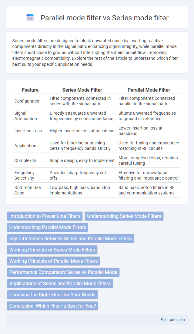
Series mode filters are designed to block unwanted noise by inserting reactive components directly in the signal path, enhancing signal integrity, while parallel mode filters shunt noise to ground without interrupting the main circuit flow, improving electromagnetic compatibility. Explore the rest of the article to understand which filter best suits your specific application needs.
Table of Comparison
| Feature | Series Mode Filter | Parallel Mode Filter |
|---|---|---|
| Configuration | Filter components connected in series with the signal path | Filter components connected parallel to the signal path |
| Signal Attenuation | Directly attenuates unwanted frequencies by series impedance | Shunts unwanted frequencies to ground or reference |
| Insertion Loss | Higher insertion loss at passband | Lower insertion loss at passband |
| Application | Used for blocking or passing certain frequency bands strictly | Used for tuning and impedance matching in RF circuits |
| Complexity | Simple design, easy to implement | More complex design, requires careful tuning |
| Frequency Selectivity | Provides sharp frequency cut-offs | Effective for narrow-band filtering and impedance control |
| Common Use Case | Low pass, high pass, band stop implementations | Band pass, notch filters in RF and communication systems |
Introduction to Power Line Filters
Power line filters reduce electromagnetic interference (EMI) by blocking unwanted noise in electrical circuits. Series mode filters attenuate differential mode noise by placing components directly in the signal path, ensuring noise travels through the filter elements, while parallel mode filters target common mode noise by shunting interference to ground without interrupting the main current flow. Your choice depends on the specific type of EMI affecting your system and the desired filtering efficiency for power line applications.
Understanding Series Mode Filters
Series mode filters are designed to suppress noise and interference by being placed directly in the signal path, allowing them to effectively block unwanted high-frequency signals while maintaining the integrity of the desired current flow. These filters typically consist of inductors and capacitors arranged to create impedance at certain frequencies, which helps reduce electromagnetic interference (EMI) in power lines or communication circuits. Series mode filtering is essential in applications requiring precise noise attenuation without altering the circuit's normal operation, such as in power supplies and audio equipment.
Understanding Parallel Mode Filters
Parallel mode filters operate by allowing the input signal to split into multiple paths, each with its own filtering elements, before recombining at the output, enhancing specific frequency ranges or attenuating unwanted signals. This configuration enables precise control over signal characteristics, making it ideal for applications requiring selective frequency filtering with minimal insertion loss. Your system benefits from improved stability and reduced noise coupling due to the parallel arrangement, compared to series mode filters where components impact the entire signal path directly.
Key Differences Between Series and Parallel Mode Filters
Series mode filters are designed to suppress common-mode noise by being inserted in series with the signal path, providing high impedance to unwanted interference while minimally affecting the desired signal. Parallel mode filters, on the other hand, target differential-mode noise by shunting unwanted signals to ground through low impedance paths placed parallel to the signal lines. The key difference lies in their noise suppression mechanism: series mode filters block noise inline, whereas parallel mode filters divert noise away from the signal path.
Working Principle of Series Mode Filters
Series mode filters operate by placing the filter components directly in the signal path, allowing them to suppress unwanted noise or interference by blocking or attenuating specific frequency ranges. This working principle ensures that all the current passes through the filter elements, effectively reducing conducted EMI and improving the overall signal integrity in power lines or communication circuits. Your devices benefit from enhanced electromagnetic compatibility as series mode filters selectively target common-mode disturbances without significantly affecting the desired signal.
Working Principle of Parallel Mode Filters
Parallel mode filters operate by allowing the input signal to split into multiple paths, each containing distinct reactive components like inductors and capacitors arranged in parallel. These filters achieve frequency selection by exploiting the resonance effects in each branch, where certain frequencies are attenuated or passed based on the impedance characteristics at those frequencies. The parallel configuration provides sharper roll-off and improved selectivity compared to series mode filters, making them suitable for applications requiring precise frequency discrimination.
Performance Comparison: Series vs Parallel Mode
Series mode filters offer higher noise attenuation and are more effective in suppressing low-frequency interference, making them ideal for sensitive equipment requiring stable signals. Parallel mode filters excel at reducing high-frequency common-mode noise with minimal insertion loss, preserving signal integrity in high-speed data applications. Understanding your system's noise characteristics helps determine whether series or parallel mode filters deliver optimal electromagnetic compatibility performance.
Applications of Series and Parallel Mode Filters
Series mode filters are widely used in power supply applications to reduce common-mode noise by blocking high-frequency interference in the signal path, ensuring cleaner DC output in devices such as smartphones and laptops. Parallel mode filters excel in EMI suppression on signal lines, making them ideal for communication systems and data transmission cables where maintaining signal integrity is critical. Both filter types are essential in automotive electronics and industrial equipment to meet stringent electromagnetic compatibility (EMC) standards and enhance system reliability.
Choosing the Right Filter for Your Needs
Series mode filters provide superior noise attenuation for applications requiring high precision, as they insert directly into the signal path, ensuring effective suppression of unwanted frequencies. Parallel mode filters operate alongside the signal path and are ideal for mitigating common-mode noise without affecting the main signal flow, making them suitable for environments with significant electromagnetic interference. Your choice depends on balancing the need for noise reduction with signal integrity and the specific interference characteristics of your system.
Conclusion: Which Filter is Best for You?
Series mode filters excel in reducing common-mode noise by placing the filter elements directly in the signal path, making them ideal for applications with stringent EMI requirements and limited space. Parallel mode filters effectively suppress differential-mode noise, perfect for circuits where signal integrity and minimal insertion loss are priorities. Selecting the best filter depends on your specific noise type and circuit design constraints, with many systems benefiting from a combination of both modes for comprehensive EMI mitigation.
Series mode filter vs Parallel mode filter Infographic