A zero-crossing detector identifies when an input signal changes sign, detecting the moment it crosses zero volts, while a window comparator checks if the input voltage lies within a specific range defined by two reference levels. Understanding these differences can help you choose the right circuit for your application--explore the full article for detailed insights.
Table of Comparison
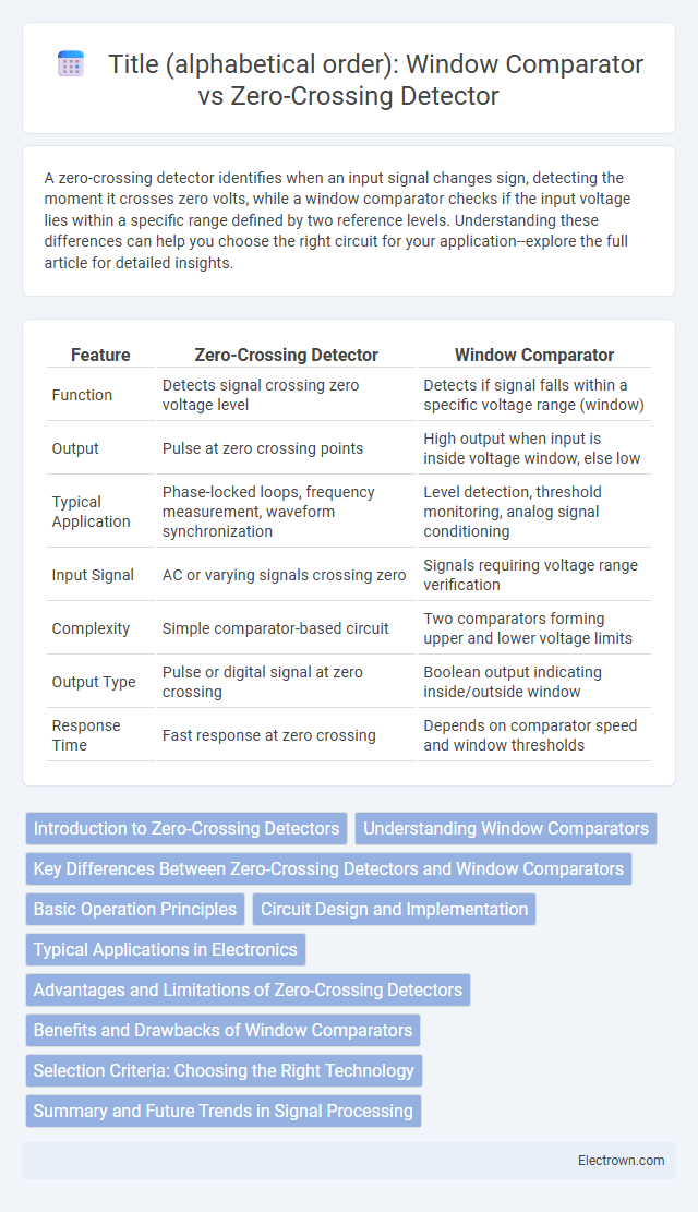
| Feature | Zero-Crossing Detector | Window Comparator |
|---|---|---|
| Function | Detects signal crossing zero voltage level | Detects if signal falls within a specific voltage range (window) |
| Output | Pulse at zero crossing points | High output when input is inside voltage window, else low |
| Typical Application | Phase-locked loops, frequency measurement, waveform synchronization | Level detection, threshold monitoring, analog signal conditioning |
| Input Signal | AC or varying signals crossing zero | Signals requiring voltage range verification |
| Complexity | Simple comparator-based circuit | Two comparators forming upper and lower voltage limits |
| Output Type | Pulse or digital signal at zero crossing | Boolean output indicating inside/outside window |
| Response Time | Fast response at zero crossing | Depends on comparator speed and window thresholds |
Introduction to Zero-Crossing Detectors
Zero-crossing detectors identify the point where an AC signal crosses the zero voltage level, enabling precise synchronization in power electronics and signal processing. These detectors convert analog signals into digital pulses by monitoring the sign change of the input waveform, making them essential in phase-locked loops and motor control systems. Unlike window comparators that detect when signals fall within a specific voltage range, zero-crossing detectors focus solely on the transition through zero, ensuring accurate timing and waveform analysis.
Understanding Window Comparators
Window comparators detect input voltages falling within a specific range, offering precise voltage level monitoring essential in applications like battery management and sensor signal processing. Unlike zero-crossing detectors that identify voltage sign changes at zero volts, window comparators use two reference voltages to establish an upper and lower threshold, ensuring output activation only when signals lie between these limits. This dual-threshold approach enables robust detection of voltage windows, improving noise immunity and system reliability in analog circuitry.
Key Differences Between Zero-Crossing Detectors and Window Comparators
Zero-crossing detectors identify the exact point where an input signal crosses the zero-voltage level, making them ideal for timing and phase detection in AC signals. Window comparators, by contrast, monitor whether an input voltage lies within a specific voltage range or "window," providing a binary output when the signal falls outside preset upper and lower thresholds. Your choice depends on whether you need precise zero-level detection or monitoring of voltage levels within defined limits for applications like signal conditioning or threshold detection.
Basic Operation Principles
A zero-crossing detector identifies the precise moment a signal waveform passes through the zero voltage level by comparing the input to ground, enabling synchronization with AC signals or waveform timing. In contrast, a window comparator uses two reference voltage levels to determine whether an input voltage lies within a specific range or window, generating output signals when the input crosses these defined thresholds. While zero-crossing detectors focus on detecting signal polarity changes at zero voltage, window comparators provide a range-based detection useful for monitoring voltage limits or signal bounds.
Circuit Design and Implementation
Zero-crossing detectors utilize operational amplifiers or comparators configured to detect when an input signal crosses the zero voltage level, providing precise timing signals for AC waveform processing. Window comparators employ dual reference voltages to create upper and lower thresholds, enabling output activation only when an input signal remains within a specified voltage range, which is ideal for level detection and monitoring. Circuit implementation of zero-crossing detectors involves minimizing phase delay and noise susceptibility, while window comparators require careful threshold selection and hysteresis design to prevent false triggering.
Typical Applications in Electronics
Zero-crossing detectors are widely used in phase-locked loops, frequency detection, and AC signal synchronization to identify the exact point where the signal changes polarity. Window comparators find typical applications in battery monitoring, voltage level detection, and over-voltage/under-voltage protection circuits by detecting if a signal falls within a predefined voltage range. Both components are essential in control systems and signal processing tasks requiring precise voltage threshold detection.
Advantages and Limitations of Zero-Crossing Detectors
Zero-crossing detectors offer the advantage of precise timing for AC signal synchronization, enabling noise reduction and efficient waveform analysis. They are limited by their sensitivity to small signal fluctuations near zero, which can cause false triggering and reduce accuracy. Your circuit design benefits from fast response times, but may require additional filtering to mitigate the effects of signal noise inherent to zero-crossing detection.
Benefits and Drawbacks of Window Comparators
Window comparators offer precise voltage range detection by monitoring whether an input signal lies within two reference thresholds, enhancing signal stability and noise immunity. Their benefits include improved accuracy in detecting signal windows and reduced false triggering compared to zero-crossing detectors, which only sense signal polarity changes at zero voltage points. However, drawbacks involve increased circuit complexity and power consumption, as well as the need for careful calibration to maintain threshold accuracy across varying temperature and component tolerances.
Selection Criteria: Choosing the Right Technology
Zero-crossing detectors excel in applications requiring precise timing for AC signal phase identification, benefiting from simple design and low cost. Window comparators are ideal when detecting voltage levels within a specific range, offering improved versatility for monitoring battery voltages or sensor outputs. Your choice depends on whether signal timing accuracy or voltage range detection aligns better with your system requirements.
Summary and Future Trends in Signal Processing
Zero-crossing detectors identify signal transitions through the zero voltage level, enabling precise timing in applications like phase-locked loops and frequency counters, while window comparators evaluate if a signal lies within specific voltage boundaries, enhancing noise immunity and signal conditioning in analog circuits. Emerging trends integrate machine learning algorithms with these traditional detectors to improve accuracy and adaptability in dynamic environments. Your future signal processing designs will increasingly leverage hybrid detectors that combine zero-crossing and window comparison techniques for optimized performance in real-time applications.
zero-crossing detector vs window comparator Infographic