Common-base amplifiers offer high voltage gain with low input impedance, making them ideal for high-frequency applications, while common-emitter amplifiers provide significant current gain and moderate voltage gain, suitable for general-purpose amplification. Explore the rest of the article to uncover which configuration best fits your electronic design needs.
Table of Comparison
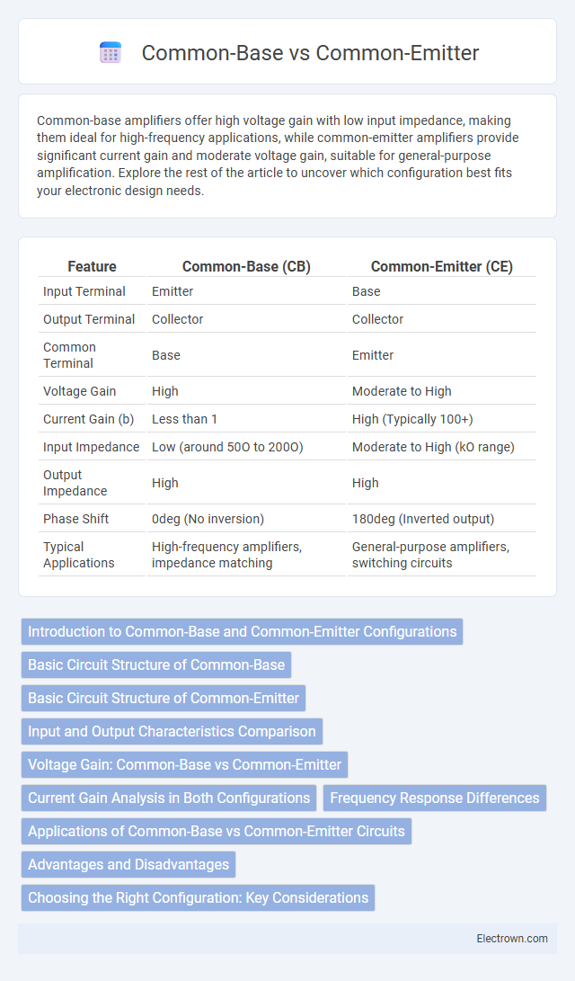
| Feature | Common-Base (CB) | Common-Emitter (CE) |
|---|---|---|
| Input Terminal | Emitter | Base |
| Output Terminal | Collector | Collector |
| Common Terminal | Base | Emitter |
| Voltage Gain | High | Moderate to High |
| Current Gain (b) | Less than 1 | High (Typically 100+) |
| Input Impedance | Low (around 50O to 200O) | Moderate to High (kO range) |
| Output Impedance | High | High |
| Phase Shift | 0deg (No inversion) | 180deg (Inverted output) |
| Typical Applications | High-frequency amplifiers, impedance matching | General-purpose amplifiers, switching circuits |
Introduction to Common-Base and Common-Emitter Configurations
Common-Base and Common-Emitter configurations are fundamental transistor configurations used in amplifier circuits. The Common-Base configuration offers low input impedance and high output impedance, suitable for high-frequency applications, while the Common-Emitter configuration provides moderate input and output impedance with significant voltage and current gain, making it ideal for general amplification purposes. Understanding these configurations helps you design circuits tailored to specific signal amplification needs and frequency ranges.
Basic Circuit Structure of Common-Base
The basic circuit structure of a common-base transistor features the base terminal grounded or connected to a fixed reference voltage, with the input signal applied to the emitter and the output taken from the collector. This configuration offers low input impedance and high voltage gain, making it suitable for high-frequency applications. Your choice between common-base and common-emitter depends on the desired input impedance and amplification characteristics.
Basic Circuit Structure of Common-Emitter
The basic circuit structure of a common-emitter amplifier includes a bipolar junction transistor (BJT) with the emitter terminal connected to ground or a reference voltage, the input signal applied at the base, and the output taken from the collector. This configuration provides significant voltage and current gain, making it widely used in amplification applications. The emitter resistor often stabilizes operating point and improves linearity, distinguishing it from the common-base setup where the base is grounded and input is applied at the emitter.
Input and Output Characteristics Comparison
The Common-Base configuration offers low input impedance and high output impedance, making it suitable for high-frequency applications with minimal input signal loss. In contrast, the Common-Emitter configuration has moderate input impedance and relatively high output impedance, providing significant voltage gain and phase inversion between input and output. Understanding these differences in input and output characteristics helps optimize Your transistor amplifier design based on specific performance requirements.
Voltage Gain: Common-Base vs Common-Emitter
Common-Emitter amplifiers typically provide high voltage gain, often ranging from 20 to 200, making them suitable for voltage amplification in audio and RF circuits. Common-Base amplifiers usually exhibit lower voltage gain, close to unity or slightly above, but offer excellent high-frequency performance and stable gain under varying conditions. The voltage gain in Common-Emitter configurations depends on the load resistance and transistor parameters, whereas Common-Base gain is largely determined by the transistor's transconductance and load resistor.
Current Gain Analysis in Both Configurations
Common-emitter configuration offers a high current gain, typically ranging from 50 to 300, making it ideal for amplification applications where signal strength needs significant increase. Common-base configuration provides a current gain slightly less than 1, primarily because the input current at the emitter directly controls the output current at the collector with minimal amplification. Your choice between the two depends on whether high current gain (common-emitter) or high-frequency stability with low input impedance (common-base) is more critical to your circuit design.
Frequency Response Differences
Common-base amplifiers exhibit superior high-frequency response due to their low input capacitance and minimal Miller effect, making them suitable for RF applications. Common-emitter configurations have higher voltage gain but suffer from reduced bandwidth because the Miller capacitance increases input capacitance, limiting high-frequency performance. Thus, common-base stages are preferred in circuits demanding wide bandwidth and high-frequency operation.
Applications of Common-Base vs Common-Emitter Circuits
Common-base circuits excel in high-frequency applications such as RF amplifiers due to their low input impedance and wide bandwidth. Common-emitter configurations are widely used in general-purpose amplification and switching because of their high voltage gain and moderate input/output impedance. While common-base stages are preferred for impedance matching in high-frequency scenarios, common-emitter circuits remain the standard choice for audio amplifiers and digital logic stages.
Advantages and Disadvantages
Common-Emitter amplifiers provide high voltage gain and moderate input impedance, making them ideal for general-purpose amplification, but they have a phase reversal between input and output which may complicate circuit design. Common-Base amplifiers offer low input impedance and high-frequency response, excelling in RF applications, but their lower input impedance limits use with high-impedance sources. Understanding your specific application needs helps determine whether the high gain of common-emitter or the superior frequency response of common-base is more advantageous.
Choosing the Right Configuration: Key Considerations
Choosing the right transistor configuration depends on the desired signal gain and input-output characteristics. Common-emitter configurations offer high voltage gain and moderate input impedance, making them suitable for amplification purposes. Common-base configurations provide low input impedance with high-frequency response, ideal for applications requiring wide bandwidth and low noise.
Common-Base vs Common-Emitter Infographic