A cascade amplifier arranges multiple stages in series to increase overall gain, whereas a cascode amplifier combines a common-emitter and a common-base stage to improve bandwidth and reduce Miller effect. Understanding the differences between cascade and cascode configurations will enhance your ability to optimize amplifier design, so read on to explore their distinct advantages and applications.
Table of Comparison
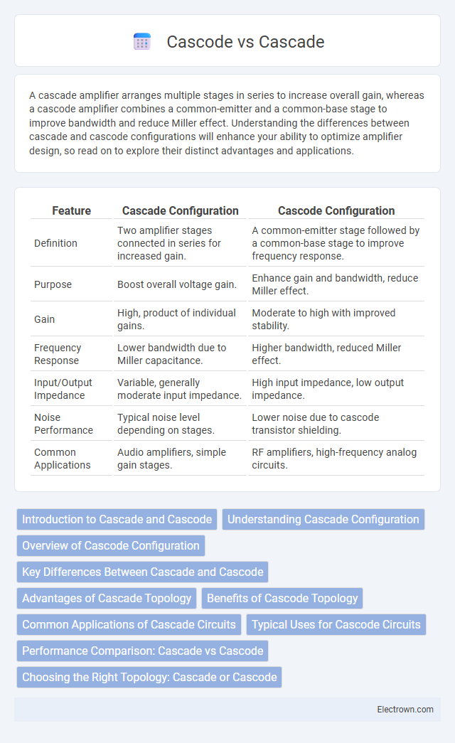
| Feature | Cascade Configuration | Cascode Configuration |
|---|---|---|
| Definition | Two amplifier stages connected in series for increased gain. | A common-emitter stage followed by a common-base stage to improve frequency response. |
| Purpose | Boost overall voltage gain. | Enhance gain and bandwidth, reduce Miller effect. |
| Gain | High, product of individual gains. | Moderate to high with improved stability. |
| Frequency Response | Lower bandwidth due to Miller capacitance. | Higher bandwidth, reduced Miller effect. |
| Input/Output Impedance | Variable, generally moderate input impedance. | High input impedance, low output impedance. |
| Noise Performance | Typical noise level depending on stages. | Lower noise due to cascode transistor shielding. |
| Common Applications | Audio amplifiers, simple gain stages. | RF amplifiers, high-frequency analog circuits. |
Introduction to Cascade and Cascode
Cascade and cascode refer to specific electronic circuit configurations primarily used in amplifiers to improve performance. A cascade circuit involves connecting two or more amplifier stages in series, where the output of one stage becomes the input of the next, enhancing voltage gain and bandwidth. The cascode configuration combines a common-emitter (or common-source) stage with a common-base (or common-gate) stage to reduce Miller capacitance and increase gain, providing higher bandwidth and improved frequency response compared to a simple cascade.
Understanding Cascade Configuration
Cascade configuration involves connecting two or more amplifying stages in series to increase overall gain while maintaining high input and low output impedance, commonly used in operational amplifiers and RF circuits. Each stage independently amplifies the signal, allowing improved bandwidth and linearity compared to a single stage with the same gain. Cascade setups differ from cascode by focusing on sequential amplification rather than the combination of common-emitter and common-base stages to reduce Miller effect and enhance frequency response.
Overview of Cascode Configuration
The cascode configuration combines a common-emitter stage followed by a common-base stage, enhancing gain and bandwidth while reducing Miller effect capacitance. This topology provides high output impedance and improved frequency response, making it ideal for high-frequency amplifier circuits. Its ability to minimize distortion and noise also benefits RF and analog signal processing applications.
Key Differences Between Cascade and Cascode
Cascade amplifiers connect multiple gain stages in series to increase overall voltage gain, while cascode amplifiers combine a common-emitter stage with a common-base stage to enhance bandwidth and reduce Miller capacitance. Cascade configurations often result in higher gain but may suffer from lower frequency response and stability issues. Cascode circuits provide improved gain-bandwidth product, higher output impedance, and better isolation between input and output signals compared to cascades.
Advantages of Cascade Topology
Cascade topology offers superior gain performance due to its multi-stage amplification, which enhances overall voltage gain compared to single-stage designs. It provides better input-output isolation, minimizing feedback and improving signal integrity in high-frequency applications. The topology also facilitates improved linearity and bandwidth, making it ideal for advanced analog circuits and RF amplifiers.
Benefits of Cascode Topology
The cascode topology offers significant benefits, including enhanced gain-bandwidth product and improved input-output isolation compared to a simple cascade configuration. Its low Miller effect leads to better high-frequency performance and increased stability in amplifier designs. Incorporating a cascode stage can improve Your circuit's linearity and reduce noise, making it a preferred choice for RF and high-speed analog applications.
Common Applications of Cascade Circuits
Cascade circuits are widely used in audio amplifiers to achieve higher gain and improved signal-to-noise ratio by stacking multiple amplifier stages. Your choice of cascade configuration enhances the frequency response and bandwidth in communication systems, making them suitable for RF signal processing. These circuits also find applications in sensor interfaces, where precise amplification of weak signals is essential for accurate data acquisition.
Typical Uses for Cascode Circuits
Cascode circuits are typically used in high-frequency amplifiers and RF applications due to their superior bandwidth and noise performance. You benefit from enhanced input-output isolation and improved gain while minimizing the Miller effect, which makes cascode configurations ideal for low-noise amplifiers (LNAs) and wideband amplifiers. Their stable gain and reduced distortion characteristics make them essential in communication systems and precision analog signal processing.
Performance Comparison: Cascade vs Cascode
Cascade and cascode amplifier configurations differ significantly in performance characteristics, with cascode amplifiers offering higher gain-bandwidth product and improved frequency response due to reduced Miller effect. The cascade configuration provides simpler design but typically suffers from lower gain and bandwidth compared to the cascode, making it less suitable for high-frequency applications. Your choice between cascade and cascode will depend on the trade-offs between complexity, gain, and frequency performance required for your circuit.
Choosing the Right Topology: Cascade or Cascode
Choosing the right topology between cascade and cascode depends on your circuit requirements for gain, bandwidth, and noise performance. Cascade amplifiers offer higher gain but typically at the expense of bandwidth and increased noise, while cascode configurations provide improved bandwidth and reduced Miller effect, enhancing frequency response and stability. Your decision should consider these trade-offs to optimize amplifier performance in high-frequency or low-noise applications.
Cascade vs Cascode Infographic