D-type flip-flops capture and store the value of the data input at every clock edge, making them ideal for data storage and synchronization tasks. Explore the rest of this article to understand how T-type flip-flops toggle their output state and determine which flip-flop best suits Your digital circuit design needs.
Table of Comparison
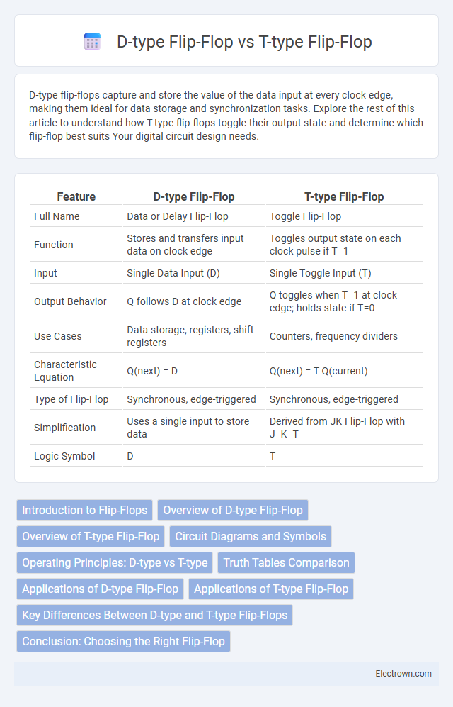
| Feature | D-type Flip-Flop | T-type Flip-Flop |
|---|---|---|
| Full Name | Data or Delay Flip-Flop | Toggle Flip-Flop |
| Function | Stores and transfers input data on clock edge | Toggles output state on each clock pulse if T=1 |
| Input | Single Data Input (D) | Single Toggle Input (T) |
| Output Behavior | Q follows D at clock edge | Q toggles when T=1 at clock edge; holds state if T=0 |
| Use Cases | Data storage, registers, shift registers | Counters, frequency dividers |
| Characteristic Equation | Q(next) = D | Q(next) = T Q(current) |
| Type of Flip-Flop | Synchronous, edge-triggered | Synchronous, edge-triggered |
| Simplification | Uses a single input to store data | Derived from JK Flip-Flop with J=K=T |
| Logic Symbol | D | T |
Introduction to Flip-Flops
Flip-flops are fundamental building blocks in digital electronics used for storing binary data and synchronizing circuits. The D-type flip-flop captures the value of the data input (D) at a clock edge, making it ideal for data storage and transfer applications. In contrast, the T-type flip-flop toggles its output state when the T input is high at the clock edge, commonly employed in counters and toggle operations.
Overview of D-type Flip-Flop
D-type Flip-Flops store a single bit of data and transfer the input (D) to the output (Q) on the triggering clock edge, making them essential for data storage and synchronization in digital circuits. They eliminate timing issues by capturing data precisely at clock transitions, ensuring reliable state retention without toggling behavior. Your designs benefit from their simple operation in registers, memory devices, and sequential logic to maintain consistent data flow.
Overview of T-type Flip-Flop
T-type Flip-Flops toggle their output state on each clock pulse when the input T is high, making them ideal for counting and frequency division applications. Unlike D-type Flip-Flops, which transfer input directly to output, T-type Flip-Flops simplify toggle operations, reducing circuit complexity in sequential logic designs. Your choice between these devices depends on whether you require straightforward data storage (D-type) or efficient state toggling (T-type).
Circuit Diagrams and Symbols
The D-type flip-flop circuit diagram features a single data input (D), a clock input (CLK), and outputs Q and Q, characterized by its straightforward symbol showing a box with D and CLK inputs and Q output. The T-type flip-flop circuit diagram includes a toggle input (T), clock input (CLK), and Q and Q outputs, with a symbol often represented by a box labeled T and CLK inputs alongside Q output, emphasizing its toggling functionality. Both flip-flops utilize standard clocked edge-triggered designs, but the D-type's symbol highlights data storage simplicity, while the T-type's symbol focuses on binary state toggling.
Operating Principles: D-type vs T-type
D-type flip-flops operate by capturing the input value (D) at the moment of a clock edge and holding it until the next clock event, effectively serving as a data latch. T-type flip-flops toggle their output state when the T input is high during the clock transition, enabling them to act as binary counters or divide-by-two circuits. The fundamental operating difference lies in the D flip-flop's data storage mechanism versus the T flip-flop's toggling behavior driven by the toggle input signal.
Truth Tables Comparison
The D-type flip-flop has a truth table where the output Q follows the input D on the clock edge, with Q+ = D, ensuring data storage without toggling behavior. The T-type flip-flop's truth table defines Q+ = T XOR Q, causing the output to toggle when T=1 and hold the current state when T=0. Comparing their truth tables highlights the D flip-flop's function as a data latch and the T flip-flop's role in state toggling, critical for counters and frequency dividers.
Applications of D-type Flip-Flop
D-type flip-flops are widely used in data storage, shift registers, and data synchronization within digital circuits due to their ability to store and transfer precise binary information on clock edges. They are essential in designing counters, memory elements, and state machines where stable and predictable output states are required. Your choice of a D-type flip-flop ensures reliable timing control and data integrity in sequential logic applications.
Applications of T-type Flip-Flop
T-type flip-flops are widely used in digital circuits for frequency division, as their toggling action effectively halves the input clock frequency with each stage, making them essential in binary counters and frequency dividers. They serve as key components in synchronous counters and memory toggle operations, where precise state changes are required based on clock pulses. The simplicity of T-type flip-flops in toggling output states facilitates implementation in timing circuits, pulse generation, and digital signal processing applications.
Key Differences Between D-type and T-type Flip-Flops
D-type flip-flops store and transfer data based on the D input, capturing the input value on the clock edge, while T-type flip-flops toggle their output state when the T input is high at the clock pulse. The D flip-flop is primarily used for data storage and synchronization, whereas the T flip-flop is commonly implemented for counting and frequency division applications. In terms of behavior, D flip-flops have a direct input-to-output data transfer, while T flip-flops change state conditionally, depending on the toggle input signal.
Conclusion: Choosing the Right Flip-Flop
Choosing the right flip-flop depends on your circuit requirements: D-type flip-flops offer simplicity and direct data storage, making them ideal for register designs and data synchronization. T-type flip-flops excel in toggling applications such as counters and frequency dividers due to their inherent toggle behavior on clock pulses. Your selection should align with whether you need straightforward data latching (D-type) or efficient binary toggling (T-type) to optimize digital system performance.
D-type Flip-Flop vs T-type Flip-Flop Infographic