Supply bypass capacitors filter high-frequency noise from power lines, ensuring stable voltage supply to electronic components, while decoupling capacitors isolate different circuit sections to prevent signal interference and voltage fluctuations. Understanding the distinct roles of these capacitors can enhance your circuit design and performance--read on to explore their applications and differences in detail.
Table of Comparison
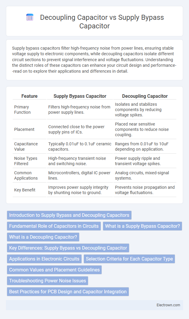
| Feature | Supply Bypass Capacitor | Decoupling Capacitor |
|---|---|---|
| Primary Function | Filters high-frequency noise from power supply lines. | Isolates and stabilizes components by reducing voltage spikes. |
| Placement | Connected close to the power supply pins of ICs. | Placed near sensitive components to reduce noise coupling. |
| Capacitance Value | Typically 0.01uF to 0.1uF ceramic capacitors. | Ranges from 0.01uF to 10uF depending on application. |
| Noise Types Filtered | High-frequency transient noise and switching noise. | Power supply ripple and transient voltage spikes. |
| Common Applications | Microcontrollers, digital IC power lines. | Analog circuits, mixed-signal systems. |
| Key Benefit | Improves power supply integrity by shunting noise to ground. | Prevents noise propagation and voltage fluctuations. |
Introduction to Supply Bypass and Decoupling Capacitors
Supply bypass capacitors are placed close to power pins of integrated circuits to filter high-frequency noise from the power supply, ensuring stable voltage levels. Decoupling capacitors serve a similar role by isolating different parts of a circuit, preventing noise generated by switching components from affecting sensitive analog or digital sections. Both capacitors improve overall circuit performance by maintaining power integrity and reducing electromagnetic interference (EMI).
Fundamental Role of Capacitors in Circuits
Supply bypass capacitors minimize voltage fluctuations by providing a low-impedance path to ground for high-frequency noise, stabilizing the power supply line. Decoupling capacitors isolate different circuit sections, preventing noise interference between components and ensuring consistent signal integrity. Your circuit's reliable performance depends on correctly selecting and placing these capacitors to effectively manage power stability and noise reduction.
What is a Supply Bypass Capacitor?
A Supply Bypass Capacitor is a passive electronic component placed close to an integrated circuit's power supply pin to filter high-frequency noise and transient voltage spikes. It provides a low-impedance path to ground for noise signals, maintaining a stable DC voltage level and preventing power supply fluctuations from affecting circuit performance. Unlike decoupling capacitors that isolate different circuit stages, supply bypass capacitors specifically mitigate interference on the power line itself.
What is a Decoupling Capacitor?
A decoupling capacitor is a critical component in electronic circuits, designed to reduce noise by providing a local energy reservoir that stabilizes voltage supply to integrated circuits. It filters out voltage spikes and high-frequency noise, preventing interference that can cause malfunctions or data corruption. Positioned close to IC power pins, decoupling capacitors enhance circuit reliability and performance by maintaining consistent power delivery under varying load conditions.
Key Differences: Supply Bypass vs Decoupling Capacitor
Supply bypass capacitors are primarily used to filter high-frequency noise from the power supply line, preventing it from affecting the circuit's operation, while decoupling capacitors focus on stabilizing voltage levels by absorbing voltage spikes and providing instantaneous current to ICs. Supply bypass capacitors are typically placed close to the power source, whereas decoupling capacitors are positioned near active components to smooth out localized fluctuations. Understanding these distinctions helps optimize your circuit's performance by ensuring proper noise reduction and voltage stability.
Applications in Electronic Circuits
Supply bypass capacitors are primarily used in power supply circuits to filter out high-frequency noise and stabilize voltage levels, ensuring clean power delivery to sensitive components. Decoupling capacitors are strategically placed near integrated circuits (ICs) to suppress voltage spikes and transient disturbances caused by rapid switching activities, improving overall circuit performance. Both capacitors enhance signal integrity and reduce electromagnetic interference (EMI) in digital and analog electronic systems.
Selection Criteria for Each Capacitor Type
Supply bypass capacitors are selected based on their ability to filter high-frequency noise close to power pins, emphasizing low equivalent series resistance (ESR) and inductance; ceramic capacitors with values ranging from 0.01uF to 0.1uF are typical choices. Decoupling capacitors require a broader value range, often combining multiple capacitors (e.g., 0.1uF and 10uF) to stabilize voltage rails against varying load conditions and transient currents, prioritizing capacitance value and mounting proximity to sensitive ICs. Your selection should consider the frequency spectrum of noise, board layout constraints, and the specific transient load requirements of your circuit.
Common Values and Placement Guidelines
Supply bypass capacitors typically range from 0.01uF to 0.1uF and are placed as close as possible to the power pins of integrated circuits to filter high-frequency noise. Decoupling capacitors often combine values such as 0.1uF ceramic capacitors in parallel with larger electrolytic capacitors (1uF to 10uF) to stabilize the supply voltage and reduce transient voltage drops, positioned near the load devices. Proper placement involves minimizing lead length and ensuring low impedance paths to ground to maximize filtering efficiency and maintain signal integrity.
Troubleshooting Power Noise Issues
Supply bypass capacitors and decoupling capacitors both mitigate power noise, but supply bypass capacitors primarily filter high-frequency transient noise near the power source, improving overall stability. Decoupling capacitors are strategically placed close to integrated circuits to smooth voltage fluctuations caused by switching currents, ensuring local power integrity. Effective troubleshooting requires measuring voltage ripple and noise at both capacitor points to identify if noise originates from supply lines or local IC switching.
Best Practices for PCB Design and Capacitor Integration
Effective PCB design integrates supply bypass capacitors close to IC power pins to minimize high-frequency noise and voltage spikes, ensuring stable power delivery. Decoupling capacitors distribute power and filter noise across the PCB, typically positioned near power supply entries and critical components to maintain signal integrity. To optimize your circuit's performance, select capacitors with appropriate values and low equivalent series resistance (ESR), and place them with minimal trace length to reduce inductance and enhance transient response.
Supply Bypass Capacitor vs Decoupling Capacitor Infographic