Lumped elements concentrate electrical properties like resistance, capacitance, and inductance into discrete components, simplifying circuit analysis but limiting accuracy at high frequencies. Distributed elements model these properties continuously along a transmission line, capturing wave behavior essential for your high-frequency designs. Explore the rest of the article to understand when to apply each model effectively.
Table of Comparison
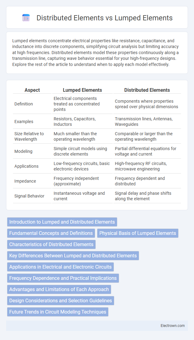
| Aspect | Lumped Elements | Distributed Elements |
|---|---|---|
| Definition | Electrical components treated as concentrated points | Components where properties spread over physical dimensions |
| Examples | Resistors, Capacitors, Inductors | Transmission lines, Antennas, Waveguides |
| Size Relative to Wavelength | Much smaller than the operating wavelength | Comparable or larger than the operating wavelength |
| Modeling | Simple circuit models using discrete elements | Partial differential equations for voltage and current |
| Applications | Low-frequency circuits, basic electronic devices | High-frequency RF circuits, microwave engineering |
| Impedance | Frequency independent (approximate) | Frequency dependent and distributed |
| Signal Behavior | Instantaneous voltage and current | Signal delay and phase shifts along the element |
Introduction to Lumped and Distributed Elements
Lumped elements are idealized circuit components assumed to have all their electrical properties concentrated at a single point, making them suitable for low-frequency circuit analysis. Distributed elements consider the spatial distribution of resistance, inductance, capacitance, and conductance along a transmission line, essential in high-frequency and microwave engineering. Understanding the distinction between lumped and distributed elements enables accurate modeling and simulation of electronic circuits across different frequency ranges.
Fundamental Concepts and Definitions
Lumped elements refer to circuit components such as resistors, capacitors, and inductors whose physical dimensions are much smaller than the wavelength of the signals they handle, allowing their electrical properties to be assumed concentrated at a single point. Distributed elements describe components like transmission lines or antennas where voltage, current, and impedance vary continuously along their length, modeled using parameters per unit length such as resistance, inductance, capacitance, and conductance. Understanding the fundamental difference hinges on the spatial scale relative to the signal wavelength, dictating whether circuit behavior is approximated by idealized, localized components or by distributed parameter models.
Physical Basis of Lumped Elements
Lumped elements assume that electrical properties such as resistance, capacitance, and inductance are concentrated at discrete points, ignoring the electromagnetic wave propagation effects due to their small size relative to the wavelength. The physical basis relies on the circuit dimensions being significantly smaller than the signal wavelength, allowing voltage and current to be well-defined at specific nodes. This approximation breaks down at high frequencies when the element size approaches the signal wavelength, necessitating distributed element models.
Characteristics of Distributed Elements
Distributed elements exhibit voltage and current that vary along their physical length, making their behavior frequency-dependent and requiring transmission line theory for accurate analysis. They are typically used in high-frequency applications where wavelength is comparable to circuit dimensions, such as antennas, microwave circuits, and RF filters. Your designs involving distributed elements must consider parameters like characteristic impedance, propagation delay, and signal reflection to ensure optimal performance.
Key Differences Between Lumped and Distributed Elements
Lumped elements, such as resistors, capacitors, and inductors, are idealized components assumed to have all their properties concentrated at a single point with negligible spatial dimensions, making them suitable for low-frequency circuit analysis. Distributed elements, like transmission lines and antennas, have physical lengths comparable to the signal wavelength, causing voltage and current to vary along their length, requiring complex modeling using distributed parameter theory. Understanding these key differences helps optimize Your circuit design by choosing appropriate models based on frequency and spatial considerations.
Applications in Electrical and Electronic Circuits
Lumped elements such as resistors, capacitors, and inductors are widely used in low-frequency electrical and electronic circuits where components can be treated as discrete units with concentrated properties. Distributed elements, including transmission lines and waveguides, are essential for high-frequency applications like RF communication and microwave engineering, where signal behavior depends on spatial variation along the circuit. Understanding these distinctions allows you to design efficient systems by selecting the appropriate model based on frequency and circuit size.
Frequency Dependence and Practical Implications
Lumped elements, such as resistors, capacitors, and inductors, operate effectively at low frequencies where their physical size is much smaller than the signal wavelength, minimizing frequency-dependent behavior. Distributed elements, like transmission lines, exhibit frequency-dependent characteristics because their physical dimensions are comparable to the signal wavelength, causing variations in impedance and signal propagation with frequency. In practical applications, lumped elements are preferred for low-frequency circuit design due to simplicity, while distributed elements are essential in high-frequency RF and microwave circuits to accurately account for signal delay and loss.
Advantages and Limitations of Each Approach
Lumped elements simplify circuit analysis with discrete components, offering ease of design and simulation, but their accuracy diminishes at high frequencies or in large-scale systems where parasitic effects dominate. Distributed elements model the physical properties of components as continuous parameters, providing precise representation for high-frequency and microwave applications, though they require complex mathematical modeling and intensive computational resources. Choosing between lumped and distributed elements depends on the frequency range, circuit size, and accuracy requirements for optimal electronic system performance.
Design Considerations and Selection Guidelines
Design considerations for lumped vs distributed elements hinge on frequency, size, and circuit complexity, where lumped elements are ideal for low-frequency, compact designs with discrete components and distributed elements suit high-frequency applications requiring transmission line modeling. Selection guidelines emphasize the electrical length relative to the signal wavelength, with lumped elements preferred when circuit dimensions are much smaller than the wavelength and distributed elements necessary when dimensions approach or exceed a significant fraction of the wavelength. Your design efficiency improves by matching element type to operational frequency and physical constraints, ensuring optimal performance and minimizing signal distortion.
Future Trends in Circuit Modeling Techniques
Future trends in circuit modeling techniques emphasize the integration of lumped and distributed elements through advanced multi-scale simulation tools, enabling more accurate representation of high-frequency and nano-scale devices. Machine learning algorithms are increasingly applied to optimize model parameters and predict complex behaviors, enhancing design efficiency and reliability. By adopting these innovations, your circuit development process will benefit from improved precision and reduced time-to-market in emerging semiconductor technologies.
Lumped vs Distributed Elements Infographic