Virtual ground circuits create a reference point within active devices that simulate a ground level, allowing signals to be processed with respect to this artificial zero voltage. Understanding the differences and applications of virtual ground versus real ground can improve your circuit design efficiency and signal accuracy--explore the full article to learn how.
Table of Comparison
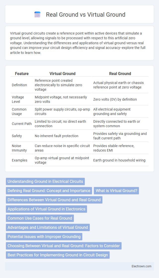
| Feature | Virtual Ground | Real Ground |
|---|---|---|
| Definition | Reference point created electronically to simulate zero voltage | Actual physical earth or chassis reference point at zero voltage |
| Voltage Level | Midpoint voltage, not necessarily zero volts | Zero volts (0V) by definition |
| Common Usage | Split power supply circuits, op-amp circuits | All electrical equipment grounding and safety |
| Current Path | Limited to circuit; no direct earth connection | Directly connected to earth or system common |
| Safety | No inherent fault protection | Provides safety via grounding and fault current path |
| Noise Immunity | Can reduce noise in specific circuit areas | Provides stable reference, reduces EMI |
| Examples | Op-amp virtual ground at midpoint voltage | Earth ground in household wiring |
Understanding Ground in Electrical Circuits
Virtual ground is an artificial reference point in electrical circuits that maintains a stable voltage, often at zero volts, created using operational amplifiers to simulate a ground potential where a real ground is not practical. Real ground refers to a physical connection to the earth or a common conductive path within the circuit, essential for safety, noise reduction, and a return path for current. Understanding the difference helps you design circuits with proper voltage references and ensures reliable signal integrity and circuit operation.
Defining Real Ground: Concept and Importance
Real ground serves as the actual reference point in electrical circuits, connecting directly to the earth or a common conductive path ensuring zero voltage potential. It provides a stable baseline essential for circuit safety, noise reduction, and accurate signal measurement. Unlike virtual ground, real ground dissipates excess electrical charge and safeguards equipment from voltage fluctuations.
What is Virtual Ground?
Virtual ground is a reference point within an electronic circuit that acts like a real ground but does not connect directly to the earth or chassis. It provides a stable voltage level, often set at half the supply voltage, enabling dual-supply operation in single-supply systems. Operational amplifiers frequently create virtual grounds to facilitate balanced signal processing without requiring a physical ground connection.
Differences Between Virtual Ground and Real Ground
Virtual ground is an artificial reference point created within a circuit, often at a mid-supply voltage, while real ground is the actual physical connection to earth or circuit common return path. Real ground provides a stable zero-voltage reference crucial for safety and noise reduction, whereas virtual ground can shift based on circuit conditions and does not connect to earth. The main difference lies in stability and reference nature: real ground is fixed and universal, whereas virtual ground is circuit-dependent and used primarily to simplify dual power supply designs.
Applications of Virtual Ground in Electronics
Virtual ground circuits are widely used in single-supply operational amplifier designs, enabling mid-supply reference points for analog signal processing without the need for dual power supplies. These circuits facilitate balanced signals in active filters, audio amplifiers, and sensor interfacing by providing a stable reference voltage that mimics real ground potential. Your electronic projects benefit from virtual ground implementation by improving signal accuracy and simplifying power supply requirements in low-voltage systems.
Common Use Cases for Real Ground
Real ground serves as the true earth reference point in electrical systems, providing safety by preventing electrical shock and ensuring stable voltage levels. It is commonly used in power distribution networks, household wiring, and sensitive electronic equipment to dissipate fault currents safely. Your circuits rely on real ground to maintain proper operation and protect against voltage surges and electrical noise.
Advantages and Limitations of Virtual Ground
Virtual ground offers advantages such as simplified circuit design, reduced component count, and improved signal stability by providing a stable midpoint voltage reference without a direct connection to the physical earth ground. Its limitations include potential drift due to op-amp offset voltages, limited current driving capability, and susceptibility to noise, which can affect circuit accuracy and performance. Understanding these trade-offs allows you to optimize your circuit for applications requiring split power supplies or isolated reference points.
Potential Issues with Improper Grounding
Improper grounding in circuits can lead to noise interference, causing signal distortion and unreliable operation, especially when virtual ground and real ground are not correctly distinguished. Virtual grounds can create unexpected current loops or voltage offsets if mistakenly treated as real ground, resulting in potential component damage or erratic behavior. Ensuring proper grounding eliminates these issues and protects the integrity of your electronic system's performance.
Choosing Between Virtual and Real Ground: Factors to Consider
When choosing between virtual ground and real ground in electronic circuit design, factors such as signal integrity, noise susceptibility, and application requirements are critical. Virtual ground provides a stable reference point in circuits without a physical earth connection, ideal for single-supply op-amp configurations, while real ground offers a true earth reference essential for safety and high-power systems. Designers must consider power consumption, circuit complexity, and noise immunity to determine the optimal grounding approach for reliable performance.
Best Practices for Implementing Ground in Circuit Design
Implementing a real ground in circuit design requires a low-impedance path that connects directly to earth or a chassis to ensure safety and minimize noise. Virtual ground, often created through active circuitry, provides a stable reference voltage in dual-supply single-rail systems but demands careful layout to avoid unintended current loops and signal distortion. Best practices include separating analog and digital grounds, using star grounding techniques, and placing virtual ground circuits close to their respective loads to maintain signal integrity and minimize electromagnetic interference.
Virtual Ground vs Real Ground Infographic