Wilkinson dividers offer superior isolation and low insertion loss, making them ideal for applications requiring signal integrity, while resistive dividers provide simple, broadband power splitting at the cost of higher signal attenuation. Discover which divider best suits your needs by exploring the detailed comparison ahead.
Table of Comparison
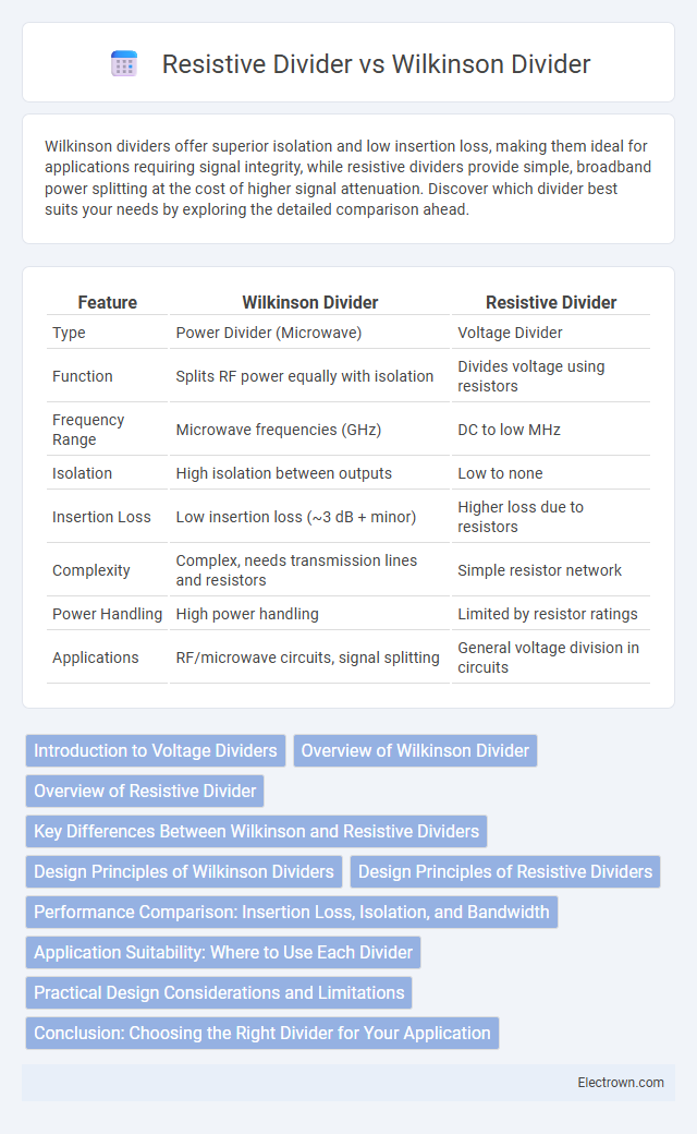
| Feature | Wilkinson Divider | Resistive Divider |
|---|---|---|
| Type | Power Divider (Microwave) | Voltage Divider |
| Function | Splits RF power equally with isolation | Divides voltage using resistors |
| Frequency Range | Microwave frequencies (GHz) | DC to low MHz |
| Isolation | High isolation between outputs | Low to none |
| Insertion Loss | Low insertion loss (~3 dB + minor) | Higher loss due to resistors |
| Complexity | Complex, needs transmission lines and resistors | Simple resistor network |
| Power Handling | High power handling | Limited by resistor ratings |
| Applications | RF/microwave circuits, signal splitting | General voltage division in circuits |
Introduction to Voltage Dividers
Voltage dividers are essential circuits used to scale down voltage levels for various electronic applications. The Wilkinson divider, a microwave frequency power splitter, offers isolation and equal power division with minimal loss, ideal for RF systems. Resistive dividers rely on passive resistors to achieve precise voltage scaling but introduce power loss and lack isolation, making them suitable for low-frequency or low-power scenarios.
Overview of Wilkinson Divider
Wilkinson Divider is a type of power divider that provides equal-split signal outputs with high isolation between ports and minimal insertion loss, making it ideal for RF and microwave applications. It utilizes quarter-wavelength transmission lines and resistors to achieve both impedance matching and isolation, ensuring signal integrity and reducing crosstalk. Unlike resistive dividers, Wilkinson Dividers maintain signal power efficiently, enhancing performance in communication systems and phased-array antennas.
Overview of Resistive Divider
Resistive dividers use a series of resistors to proportionally split voltage signals, providing a simple and cost-effective method for voltage division. They offer broadband frequency performance but introduce insertion loss and limited power handling compared to Wilkinson dividers, which use transmission line couplers to achieve equal power split with isolation and minimal loss. Your choice depends on the application's frequency range, power requirements, and the need for isolation between output ports.
Key Differences Between Wilkinson and Resistive Dividers
Wilkinson dividers provide low-loss signal splitting with excellent isolation between output ports, making them ideal for high-frequency applications above 1 GHz. Resistive dividers offer broadband performance and simple design but introduce higher insertion loss and poor isolation, limiting their use to low-frequency or low-precision scenarios. The Wilkinson's performance relies on quarter-wavelength transmission lines and isolating resistors, while resistive dividers use simple resistor networks without transmission line effects.
Design Principles of Wilkinson Dividers
Wilkinson dividers use quarter-wave transformers and resistive elements to achieve equal power division with high isolation between output ports, enhancing signal integrity in RF circuits. Their design principles rely on controlling impedance matching and minimizing insertion loss, ensuring efficient signal splitting without reflection. Your choice of a Wilkinson divider benefits applications requiring precise phase and amplitude balance, crucial in communication systems and phased array antennas.
Design Principles of Resistive Dividers
Resistive dividers operate on the principle of voltage division using a series of resistors, where the output voltage is a fraction of the input determined by the ratio of resistor values. The design focuses on selecting precision resistors to achieve accurate and stable voltage levels, while minimizing power loss and ensuring linear behavior across the operating frequency range. Your circuit's performance depends on careful consideration of resistor tolerance, thermal stability, and loading effects to maintain signal integrity.
Performance Comparison: Insertion Loss, Isolation, and Bandwidth
Wilkinson dividers exhibit low insertion loss typically around 0.5 dB due to their matched ports and isolation resistors, providing superior isolation often exceeding 20 dB across a wide bandwidth, which makes them ideal for RF and microwave applications. Resistive dividers, in contrast, have higher insertion loss usually above 6 dB and limited isolation since they rely on resistive elements without active matching, resulting in poor isolation and narrower operational bandwidth. Consequently, Wilkinson dividers deliver higher performance in terms of insertion loss, isolation, and bandwidth, making them preferred for precision signal splitting in high-frequency circuits.
Application Suitability: Where to Use Each Divider
Wilkinson dividers are ideal for high-frequency RF and microwave circuits requiring low insertion loss, high isolation, and matched ports, making them suitable for applications like power splitting in antenna arrays and signal distribution in communication systems. Resistive dividers excel in broadband applications and low-frequency circuits where simplicity, cost-effectiveness, and impedance matching across a wide frequency range are prioritized, such as audio signal splitting and general-purpose test equipment. Choosing between them depends on application-specific requirements for frequency, power handling, insertion loss, and isolation performance.
Practical Design Considerations and Limitations
Wilkinson Dividers provide excellent isolation and low insertion loss, making them suitable for high-frequency applications, but they require precise impedance matching and bulky quarter-wave transformers that limit miniaturization. Resistive Dividers offer simplicity and broadband performance with easy integration, yet they suffer from higher insertion loss and poor isolation, reducing their efficiency in power-sensitive systems. Designers must balance the Wilkinson Divider's complexity and size against the Resistive Divider's signal degradation and thermal dissipation challenges to select the best option for specific RF circuit requirements.
Conclusion: Choosing the Right Divider for Your Application
Wilkinson dividers provide superior isolation and minimal signal loss, making them ideal for high-frequency and microwave applications requiring precise power splitting. Resistive dividers offer simplicity and broadband performance but suffer from higher insertion loss and poor isolation, suitable for low-frequency or less critical applications. Your choice depends on balancing performance needs with cost and complexity constraints specific to your project.
Wilkinson Divider vs Resistive Divider Infographic