Boost PFC uses an inductor and a switch to step up voltage while shaping current to improve power factor, making it ideal for single-stage power supplies. Bridgeless PFC eliminates the diode bridge to reduce conduction losses and enhance efficiency in high-power applications; explore the rest of the article to discover which PFC approach suits Your needs best.
Table of Comparison
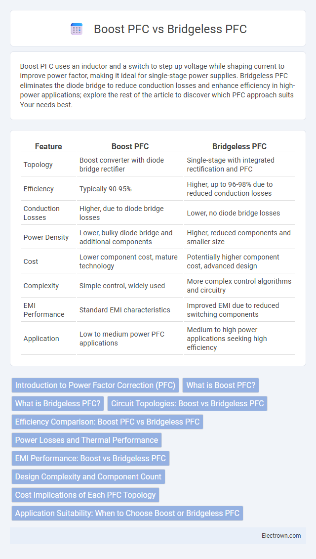
| Feature | Boost PFC | Bridgeless PFC |
|---|---|---|
| Topology | Boost converter with diode bridge rectifier | Single-stage with integrated rectification and PFC |
| Efficiency | Typically 90-95% | Higher, up to 96-98% due to reduced conduction losses |
| Conduction Losses | Higher, due to diode bridge losses | Lower, no diode bridge losses |
| Power Density | Lower, bulky diode bridge and additional components | Higher, reduced components and smaller size |
| Cost | Lower component cost, mature technology | Potentially higher component cost, advanced design |
| Complexity | Simple control, widely used | More complex control algorithms and circuitry |
| EMI Performance | Standard EMI characteristics | Improved EMI due to reduced switching components |
| Application | Low to medium power PFC applications | Medium to high power applications seeking high efficiency |
Introduction to Power Factor Correction (PFC)
Power Factor Correction (PFC) improves the efficiency of electrical systems by minimizing reactive power and enhancing power quality. Boost PFC uses an inductor and a switch to reshape the input current waveform, achieving near-unity power factor. Bridgeless PFC eliminates the input diode bridge, reducing conduction losses and increasing overall efficiency, making your electrical design more energy-efficient.
What is Boost PFC?
Boost PFC (Power Factor Correction) is a widely used technique in power electronics designed to improve the power factor by shaping the input current to be in phase with the input voltage, thereby reducing harmonic distortion and increasing efficiency. It utilizes a single boost converter stage that operates by switching a transistor rapidly to control the input current and maintain a stable DC bus voltage. Compared to bridgeless PFC, boost PFC offers simplicity and cost-effectiveness but may experience higher conduction losses due to the presence of a full-bridge diode rectifier.
What is Bridgeless PFC?
Bridgeless Power Factor Correction (PFC) is a topological design that eliminates the traditional input diode bridge rectifier, resulting in reduced conduction losses and improved efficiency in power supplies. Unlike boost PFC, which uses a diode bridge, bridgeless PFC directly connects the AC input to the PFC stage, minimizing voltage drops and heat dissipation. Your power systems benefit from higher power density and better thermal performance when implementing bridgeless PFC compared to conventional boost PFC solutions.
Circuit Topologies: Boost vs Bridgeless PFC
Boost Power Factor Correction (PFC) circuits utilize a single active switch and an inductor to shape the input current, offering a simple topology with good efficiency under moderate load conditions. Bridgeless PFC circuits eliminate the input diode bridge, reducing conduction losses by using two active switches and split inductors, which improves efficiency especially at higher power levels. Your choice between boost and bridgeless PFC topology depends on the balance between design complexity, component count, and the desired efficiency performance.
Efficiency Comparison: Boost PFC vs Bridgeless PFC
Boost Power Factor Correction (PFC) circuits typically achieve efficiency rates around 95% due to their simpler topology and fewer conduction losses. Bridgeless PFC designs improve efficiency further by eliminating the input diode bridge, reducing conduction losses, and can reach efficiency levels above 97%. When optimizing your power supply, choosing bridgeless PFC can enhance overall system efficiency and reduce thermal stress compared to traditional boost PFC configurations.
Power Losses and Thermal Performance
Boost PFC circuits exhibit higher conduction losses due to their continuous current flow through the inductor and diode, resulting in increased power dissipation and thermal stress on components. Bridgeless PFC designs reduce power losses by eliminating the input rectifier bridge, thereby minimizing diode voltage drops and enhancing overall efficiency, which directly improves thermal performance. Your choice between these topologies impacts system reliability and cooling requirements, with bridgeless PFC generally offering superior thermal management in high-power applications.
EMI Performance: Boost vs Bridgeless PFC
Boost PFC converters typically exhibit higher EMI levels due to the switching noise generated by the input inductor and diode bridge configuration. Bridgeless PFC designs reduce EMI emissions by eliminating the diode bridge, which decreases conduction losses and switching noise, resulting in improved electromagnetic compatibility. Your choice between boost and bridgeless PFC should consider EMI performance requirements, especially in applications demanding low electromagnetic interference.
Design Complexity and Component Count
Boost PFC features a simpler design with a lower component count, making it easier to implement and maintain compared to bridgeless PFC. Bridgeless PFC reduces conduction losses but requires a more complex control strategy and additional components, increasing overall design complexity. Choosing your preferred solution depends on balancing efficiency goals with system complexity and component costs.
Cost Implications of Each PFC Topology
Boost PFC topologies generally incur higher costs due to the need for bulky EMI filters and additional passive components, increasing board space and material expenses. Bridgeless PFC designs eliminate the input diode bridge, reducing conduction losses and improving efficiency, which can lower thermal management requirements and associated costs. Despite higher initial component costs, bridgeless PFC topologies offer long-term savings in energy and cooling, making them more cost-effective in high-power applications.
Application Suitability: When to Choose Boost or Bridgeless PFC
Boost PFC is ideal for applications requiring high power factor correction in environments with moderate efficiency demands and cost constraints, such as consumer electronics and general-purpose power supplies. Bridgeless PFC suits high-power, high-efficiency applications like servers and telecom systems where reduced conduction losses and thermal stress are critical. Selecting between Boost and Bridgeless PFC depends on the specific efficiency, cost, and thermal management priorities of the power supply design.
boost pfc vs bridgeless pfc Infographic