Series resonant inverters operate at resonance frequency where inductive and capacitive reactances cancel each other, resulting in minimal impedance and maximum current flow, ideal for applications requiring high current and low voltage. Parallel resonant inverters provide high impedance at resonance, ensuring minimal current flow and stable voltage, making them suitable for voltage-sensitive tasks; explore the rest of the article to understand which inverter best fits Your needs.
Table of Comparison
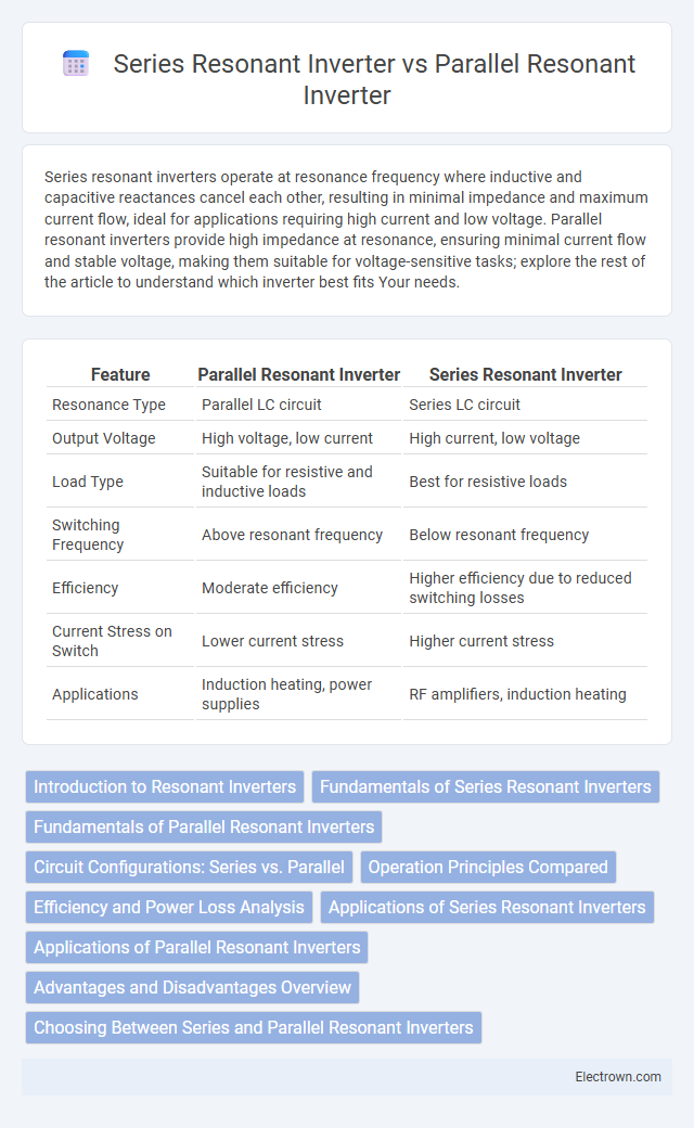
| Feature | Parallel Resonant Inverter | Series Resonant Inverter |
|---|---|---|
| Resonance Type | Parallel LC circuit | Series LC circuit |
| Output Voltage | High voltage, low current | High current, low voltage |
| Load Type | Suitable for resistive and inductive loads | Best for resistive loads |
| Switching Frequency | Above resonant frequency | Below resonant frequency |
| Efficiency | Moderate efficiency | Higher efficiency due to reduced switching losses |
| Current Stress on Switch | Lower current stress | Higher current stress |
| Applications | Induction heating, power supplies | RF amplifiers, induction heating |
Introduction to Resonant Inverters
Resonant inverters, including parallel resonant and series resonant types, use resonance between inductive and capacitive components to convert DC to AC with high efficiency and reduced switching losses. Parallel resonant inverters have the LC tank circuit connected in parallel with the load, optimizing voltage control and minimizing current stress on the switching devices. Series resonant inverters place the LC tank in series with the load, allowing precise current regulation and operation at the resonant frequency for improved power transfer and reduced harmonic distortion.
Fundamentals of Series Resonant Inverters
Series resonant inverters operate by creating a resonant tank circuit where inductors and capacitors are connected in series, enabling efficient energy transfer at the resonant frequency. This configuration results in high current flow through the load while maintaining a constant voltage, making it ideal for applications requiring precise control. Understanding the fundamental principles of series resonant inverters helps optimize Your power conversion systems for minimal losses and enhanced performance.
Fundamentals of Parallel Resonant Inverters
Parallel resonant inverters operate by tuning the circuit's inductance and capacitance to resonate at a specific frequency, creating a high impedance path at resonance that controls current flow. This resonance condition causes the voltage to peak while the current minimizes, making these inverters ideal for driving inductive or capacitive loads with minimal current distortion. Your understanding of the fundamental principle that the switched elements work efficiently under zero-current switching improves inverter performance and reduces energy losses.
Circuit Configurations: Series vs. Parallel
Series resonant inverters feature a circuit configuration where the load is connected in series with the resonant inductor and capacitor, forming a series LC circuit that allows current resonance at the resonant frequency. Parallel resonant inverters use a configuration where the resonant inductor and capacitor are connected in parallel with the load, creating a parallel LC circuit that controls voltage resonance. The series configuration emphasizes current control and tends to provide low current at resonance, while the parallel configuration targets voltage regulation with high impedance at the resonant frequency.
Operation Principles Compared
Parallel resonant inverters operate by creating a high impedance at the resonant frequency, causing the current to lag the voltage and resulting in a voltage-driven circuit that minimizes current flow through the switching devices. Series resonant inverters, in contrast, have a low impedance path at resonance, making the current in phase with the voltage and forming a current-driven circuit where the current is determined by the load and resonant components. The fundamental difference lies in how the resonant tank circuit--parallel or series--affects the current and voltage waveforms, influencing the efficiency and control characteristics of the inverter.
Efficiency and Power Loss Analysis
Parallel resonant inverters typically exhibit higher efficiency at lighter loads due to reduced current stress and lower conduction losses, whereas series resonant inverters maintain better efficiency under heavy load conditions by minimizing switching losses. Power loss in parallel resonant inverters arises mainly from circulating currents within the tank circuit, while series resonant inverters experience losses primarily through the series components' resistance and device switching behavior. Your choice depends on the load profile and required efficiency, with series resonant inverters preferred for constant heavy loads and parallel resonant inverters suited for variable or light loads.
Applications of Series Resonant Inverters
Series resonant inverters are widely used in induction heating, wireless power transfer, and RF amplification due to their ability to handle high-frequency operations efficiently. Their high current gain and ability to operate at resonance make them ideal for applications requiring precise power control and minimal switching losses. Your choice of a series resonant inverter ensures optimized performance in systems demanding fast response and efficient energy conversion.
Applications of Parallel Resonant Inverters
Parallel resonant inverters are primarily used in high-frequency induction heating, lighting ballasts, and wireless power transfer systems due to their ability to maintain a constant frequency with varying load conditions. They efficiently supply power to loads modeled as parallel resonant circuits, enabling precise control of voltage and current. These inverters are advantageous in applications requiring frequency stability and reduced switching losses.
Advantages and Disadvantages Overview
Parallel resonant inverters offer advantages such as reduced switching losses and better voltage regulation due to their high impedance at resonance, making them suitable for applications requiring stable output. However, they exhibit lower current handling capability and can suffer from increased voltage stress on components. Series resonant inverters provide high current output and simpler circuit design with lower voltage stress, but they tend to have higher switching losses and less efficient voltage regulation under varying load conditions. Your choice depends on balancing efficiency, voltage stability, and current requirements for the specific application.
Choosing Between Series and Parallel Resonant Inverters
Choosing between series and parallel resonant inverters depends on your application requirements such as load type and efficiency. Series resonant inverters excel in driving inductive or capacitive loads with minimal switching losses, offering high-frequency operation and reduced electromagnetic interference. Parallel resonant inverters provide better output voltage regulation and are preferred for resistive loads, delivering stable performance under variable load conditions.
Parallel resonant vs Series resonant inverter Infographic