Miller clamp and Miller resistor both serve to reduce the Miller effect in transistor circuits, but the clamp directly limits voltage swing while the resistor provides controlled feedback to mitigate gain reduction. Understanding the differences can improve your circuit design, so read on to explore how each component impacts performance.
Table of Comparison
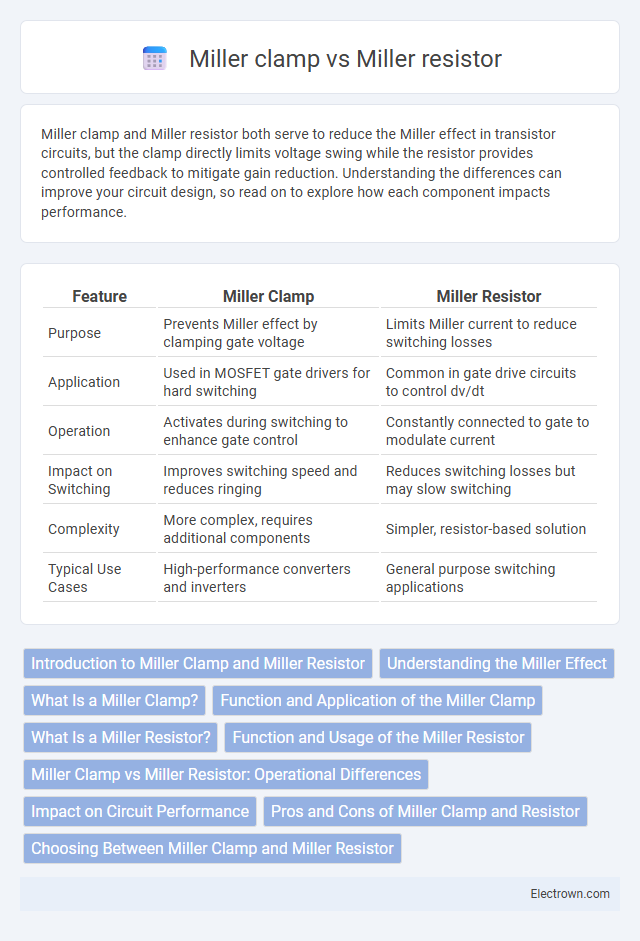
| Feature | Miller Clamp | Miller Resistor |
|---|---|---|
| Purpose | Prevents Miller effect by clamping gate voltage | Limits Miller current to reduce switching losses |
| Application | Used in MOSFET gate drivers for hard switching | Common in gate drive circuits to control dv/dt |
| Operation | Activates during switching to enhance gate control | Constantly connected to gate to modulate current |
| Impact on Switching | Improves switching speed and reduces ringing | Reduces switching losses but may slow switching |
| Complexity | More complex, requires additional components | Simpler, resistor-based solution |
| Typical Use Cases | High-performance converters and inverters | General purpose switching applications |
Introduction to Miller Clamp and Miller Resistor
Miller clamp and Miller resistor are key components used to improve switching performance in MOSFET drivers by controlling the Miller effect during transitions. The Miller clamp actively clamps the MOSFET gate to prevent unwanted turn-on caused by voltage spikes, enhancing switching speed and reducing losses. The Miller resistor, on the other hand, slows down the gate voltage change rate by inserting resistance, mitigating voltage overshoot but potentially increasing switching losses.
Understanding the Miller Effect
The Miller clamp neutralizes the Miller effect by directly shorting the gate to the drain during transistor switching, minimizing parasitic capacitance and improving switching speed. In contrast, the Miller resistor controls the Miller current through a high-value resistor, slowing the voltage transition and reducing switching noise but increasing switching losses. Understanding the Miller effect involves recognizing the amplified input capacitance formed by the gate-drain overlap, which impacts switching performance and efficiency in power electronics.
What Is a Miller Clamp?
A Miller clamp is a semiconductor circuit designed to prevent the Miller effect by stabilizing the gate voltage of a MOSFET during switching, reducing switching losses and improving efficiency. Unlike a Miller resistor, which simply limits current to control the gate voltage rise time, the Miller clamp actively clamps the gate-source voltage to a fixed level, preventing unwanted voltage spikes. This function is essential in high-frequency applications such as synchronous rectification and DC-DC converters to enhance switching performance and reduce electromagnetic interference (EMI).
Function and Application of the Miller Clamp
The Miller clamp functions by preventing the Miller effect in MOSFETs, stabilizing the gate voltage during switching to reduce switching losses and improve efficiency in power converters. It is commonly applied in synchronous buck converters and other high-frequency switching circuits to enhance performance and reduce distortion. Unlike the Miller resistor, which slows down switching speed to mitigate voltage spikes, the Miller clamp actively clamps the gate voltage, offering faster switching transitions and better control over the MOSFET's switching behavior.
What Is a Miller Resistor?
A Miller resistor is a component used in amplifier circuits to reduce the Miller effect, which causes unwanted capacitance and limits high-frequency performance. It typically connects between the input and output of an amplifier stage to neutralize the parasitic capacitance, improving bandwidth and stability. Compared to a Miller clamp, which is designed to control switching transients in power devices, the Miller resistor specifically targets frequency response optimization in analog circuits.
Function and Usage of the Miller Resistor
The Miller resistor is primarily used to control the Miller effect in amplifier circuits by reducing the gain-induced feedback capacitance, thus enhancing stability and bandwidth. Unlike the Miller clamp, which limits voltage spikes in power electronics, the Miller resistor directly impacts signal integrity by mitigating high-frequency oscillations in transistor amplifiers. Your choice of a Miller resistor influences the frequency response and noise performance in analog signal applications.
Miller Clamp vs Miller Resistor: Operational Differences
Miller clamps actively prevent the gate voltage from rising beyond a set threshold by providing a low-impedance path, effectively reducing switching losses and improving efficiency in power transistors. In contrast, Miller resistors limit the gate current during switching by introducing resistance, which slows down the voltage rise and mitigates oscillations but does not fully clamp the voltage. The operational difference lies in the clamp's ability to fix the gate voltage level directly, while the resistor manages switching speed through current limitation without voltage clamping.
Impact on Circuit Performance
Miller clamps significantly reduce the Miller effect by preventing voltage overshoot during transistor switching, improving overall circuit stability and speed. Miller resistors, on the other hand, control the rate of voltage change across the transistor, effectively managing switching losses but potentially slowing switching speed compared to clamps. Your choice between these components directly impacts switching efficiency, noise reduction, and thermal management in high-frequency or power electronic applications.
Pros and Cons of Miller Clamp and Resistor
The Miller clamp effectively reduces the Miller effect, enhancing switching speed and minimizing power loss in MOSFETs, but it adds complexity and cost to the circuit design. The Miller resistor offers a simpler, cost-effective solution with easy implementation, though it may lead to slower switching speeds and greater power dissipation. Choosing between the two depends on performance requirements, cost constraints, and circuit complexity tolerance.
Choosing Between Miller Clamp and Miller Resistor
Choosing between a Miller clamp and a Miller resistor depends on your circuit's specific needs for controlling the Miller effect in power transistors. A Miller clamp actively reduces switching losses by quickly discharging the gate during turn-off, ideal for high-frequency applications requiring fast switching. In contrast, a Miller resistor provides a passive delay to reduce voltage spikes and ringing, making it suitable for simpler or lower-frequency designs where minimizing electromagnetic interference is the priority.
Miller clamp vs Miller resistor Infographic