Diode ORing uses discrete diodes to combine power sources but suffers from voltage drop and power loss, whereas ideal diode controllers simulate diode behavior with minimal voltage drop, enhancing efficiency and reliability in power management. Discover how choosing the right method can optimize Your system's performance in the full article.
Table of Comparison
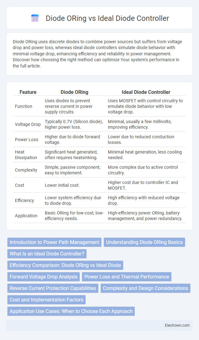
| Feature | Diode ORing | Ideal Diode Controller |
|---|---|---|
| Function | Uses diodes to prevent reverse current in power supply circuits. | Uses MOSFET with control circuitry to emulate diode behavior with low voltage drop. |
| Voltage Drop | Typically 0.7V (Silicon diode), higher power loss. | Minimal, usually a few millivolts, improving efficiency. |
| Power Loss | Higher due to diode forward voltage. | Lower due to reduced conduction losses. |
| Heat Dissipation | Significant heat generated, often requires heatsinking. | Minimal heat generation, less cooling needed. |
| Complexity | Simple, passive component; easy to implement. | More complex due to active control circuitry. |
| Cost | Lower initial cost. | Higher cost due to controller IC and MOSFET. |
| Efficiency | Lower system efficiency due to diode drop. | High efficiency with reduced voltage drop. |
| Application | Basic ORing for low-cost, low-efficiency needs. | High-efficiency power ORing, battery management, and power redundancy. |
Introduction to Power Path Management
Diode ORing and Ideal Diode Controllers play crucial roles in power path management by ensuring seamless and efficient power source switching. Diode ORing uses traditional diodes to prevent reverse current flow but suffers from voltage drops and power loss, impacting overall system efficiency. Ideal Diode Controllers, leveraging MOSFETs and advanced control circuitry, minimize conduction losses, optimize power flow, and extend battery life, enhancing reliability and performance in your power management design.
Understanding Diode ORing Basics
Diode ORing involves using diodes to combine multiple power sources, ensuring uninterrupted power supply by allowing current from the highest voltage source to flow while blocking reverse current. An ideal diode controller enhances this by using MOSFETs and control circuitry to minimize voltage drop and power loss compared to traditional diodes. Understanding Diode ORing basics is crucial for designing efficient power redundancy and load-sharing systems in applications such as telecom and data centers.
What Is an Ideal Diode Controller?
An Ideal Diode Controller is an advanced power management device designed to replace traditional diode ORing by minimizing forward voltage drop and power loss. It uses a MOSFET to emulate the behavior of a diode, offering higher efficiency and improved thermal performance in power path redundancy applications. Your system benefits from reduced energy waste and enhanced reliability when implementing an Ideal Diode Controller instead of conventional diode ORing.
Efficiency Comparison: Diode ORing vs Ideal Diode
Diode ORing typically results in higher conduction losses due to the forward voltage drop of standard diodes, leading to reduced overall efficiency in power systems. Ideal diode controllers, which use MOSFETs to emulate diode behavior with significantly lower voltage drops, enhance efficiency by minimizing power dissipation during current flow. In high-current applications, ideal diode controllers can improve efficiency by up to 5-10% compared to traditional diode ORing, making them favorable for energy-sensitive designs.
Forward Voltage Drop Analysis
Diode ORing typically experiences a significant forward voltage drop ranging from 0.3V to 0.7V depending on the diode type, which results in power loss and heat dissipation during current conduction. Ideal diode controllers leverage MOSFETs to achieve a forward voltage drop close to the RDS(on) characteristic, often in the milliohm range, dramatically reducing conduction losses compared to traditional diode ORing. This optimization in forward voltage drop directly improves efficiency and thermal performance in power systems requiring seamless diode ORing functionality.
Power Loss and Thermal Performance
Diode ORing circuits typically exhibit higher power loss due to the forward voltage drop across the diodes, resulting in increased heat generation and reduced thermal performance. Ideal diode controllers use MOSFETs with very low on-resistance, minimizing conduction losses and significantly improving efficiency and thermal management. This reduction in heat dissipation enhances system reliability and allows for more compact heat sinking solutions in power distribution designs.
Reverse Current Protection Capabilities
Diode ORing provides basic reverse current protection by preventing current from flowing back through a disconnected or failed power source, but it causes voltage drop and power loss due to the diode's forward voltage. Ideal diode controllers use MOSFETs to mimic diode behavior with significantly lower voltage drop while actively preventing reverse current, enhancing efficiency and reliability in power path management. Their ability to quickly switch off the MOSFET during reverse current events ensures superior protection and reduces energy waste compared to traditional diode ORing solutions.
Complexity and Design Considerations
Diode ORing utilizes simple, passive diodes to combine multiple power sources but suffers from voltage drop and power loss, complicating efficiency optimization in designs requiring low dropout voltages. Ideal diode controllers replace passive diodes with active MOSFET switches controlled by integrated circuits, significantly reducing forward voltage drop and improving power efficiency, though they introduce increased circuit complexity and require careful layout and thermal management. Designers must balance the simplicity and reliability of diode ORing against the superior performance and higher design demands of ideal diode controllers depending on application needs.
Cost and Implementation Factors
Diode ORing is a cost-effective solution that relies on simple diodes, resulting in lower initial expenses but with higher voltage drop and power dissipation, impacting overall efficiency. Ideal diode controllers use MOSFETs and advanced circuitry to minimize voltage drop and improve efficiency, though they come with higher component costs and increased implementation complexity. Your choice depends on balancing budget constraints with efficiency requirements and the sophistication of your power management design.
Application Use Cases: When to Choose Each Approach
Diode ORing excels in simple power redundancy systems where cost-effectiveness and simplicity are paramount, particularly in low-voltage DC applications such as telecom and server power supplies. Ideal diode controllers are preferred in high-efficiency environments requiring minimal voltage drop and power loss, commonly found in advanced battery systems, renewable energy inverters, and automotive electronics. Selecting between Diode ORing and Ideal diode controllers depends on application requirements for efficiency, complexity, and thermal management.
Diode ORing vs Ideal diode controller Infographic