A precharge circuit limits inrush current by gradually charging capacitors before full power is applied, protecting components from sudden surges, while a soft start circuit controls the output voltage or current ramp-up to prevent stress on the system during startup. Understanding the differences between these circuits can help you choose the right approach for your electronic design; explore the rest of the article to learn more.
Table of Comparison
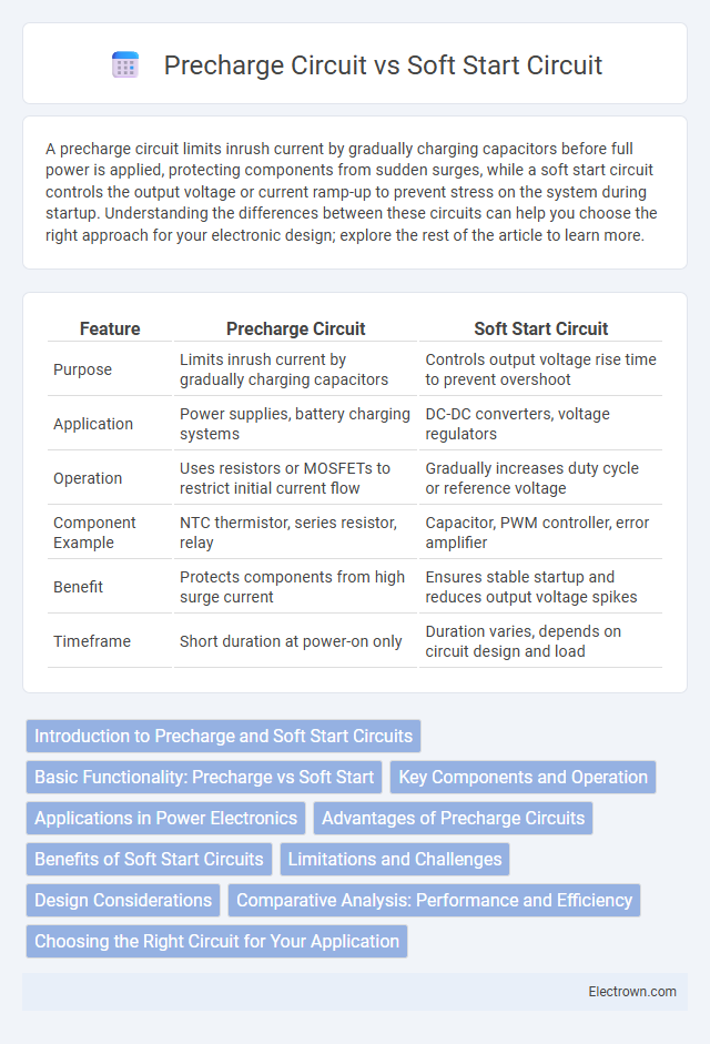
| Feature | Precharge Circuit | Soft Start Circuit |
|---|---|---|
| Purpose | Limits inrush current by gradually charging capacitors | Controls output voltage rise time to prevent overshoot |
| Application | Power supplies, battery charging systems | DC-DC converters, voltage regulators |
| Operation | Uses resistors or MOSFETs to restrict initial current flow | Gradually increases duty cycle or reference voltage |
| Component Example | NTC thermistor, series resistor, relay | Capacitor, PWM controller, error amplifier |
| Benefit | Protects components from high surge current | Ensures stable startup and reduces output voltage spikes |
| Timeframe | Short duration at power-on only | Duration varies, depends on circuit design and load |
Introduction to Precharge and Soft Start Circuits
Precharge circuits limit inrush current by gradually charging capacitors in power systems, protecting components from damage and extending device lifespan. Soft start circuits control the ramp-up of voltage or current during device startup, preventing sudden surges and improving system stability. Both circuits optimize power management and enhance reliability in electronic applications.
Basic Functionality: Precharge vs Soft Start
Precharge circuits primarily limit inrush current by gradually charging input capacitors before full power application, protecting components from voltage spikes. Soft start circuits manage the gradual increase of output voltage or current during startup to prevent sudden surges and ensure system stability. Your choice between these circuits depends on whether controlling initial capacitor charging (precharge) or overall power ramp-up (soft start) is the priority in your design.
Key Components and Operation
Precharge circuits utilize resistors and relays to gradually charge capacitors or batteries, preventing inrush current during power-up by controlling the initial current flow. Soft start circuits incorporate components like MOSFETs and operational amplifiers to smoothly ramp up voltage or current, reducing stress on power devices and improving system reliability. Understanding the key components and operation of these circuits helps you optimize power management in electronic systems.
Applications in Power Electronics
Precharge circuits are essential in power electronics for limiting inrush current when connecting high-capacitance loads to power supplies, protecting switches and extending device lifespan. Soft start circuits gradually increase the output voltage of power converters during startup, preventing voltage overshoot and reducing stress on components in applications such as DC-DC converters and motor drives. Both circuits enhance reliability and efficiency in power electronics systems by managing current and voltage transients during power-up phases.
Advantages of Precharge Circuits
Precharge circuits offer significant advantages in protecting electrical systems by limiting inrush current during power-up, which prevents component damage and extends equipment lifespan. These circuits reduce electrical stress on power supplies and minimize voltage surges, enhancing system reliability and operational stability. Precharge circuits are especially beneficial in applications involving capacitive loads or large power converters where controlled start-up is critical.
Benefits of Soft Start Circuits
Soft start circuits reduce inrush current during power-up, protecting components and extending their lifespan in power supply designs. They enhance system stability by gradually ramping voltage, preventing voltage spikes that could damage sensitive electronics. Soft start mechanisms improve overall reliability and reduce electromagnetic interference generated during startup.
Limitations and Challenges
Precharge circuits face limitations such as residual voltage inconsistencies and limited control over inrush current, potentially causing stress on components during startup. Soft start circuits encounter challenges in balancing the ramp-up time to prevent DC bus voltage overshoot while maintaining efficient startup speed. Both circuits demand precise design to avoid thermal stress and enhance system reliability in power electronics applications.
Design Considerations
Design considerations for precharge circuits focus on managing inrush current through controlled initial charging of capacitors, which helps protect power components and ensures system stability. Soft start circuits prioritize gradually ramping up voltage or current to avoid sudden power surges, enhancing the longevity of your electronic devices and minimizing electromagnetic interference. Selecting between these circuits depends on the specific application requirements, such as load characteristics and desired startup behavior.
Comparative Analysis: Performance and Efficiency
Precharge circuits limit inrush current by charging input capacitors gradually, enhancing component longevity and reducing stress on power supplies. Soft start circuits control the ramp-up of output voltage, minimizing voltage overshoot and ensuring smooth power delivery to your load. Both techniques improve system reliability, but precharge circuits primarily focus on current management, whereas soft start circuits optimize voltage stabilization for efficient startup performance.
Choosing the Right Circuit for Your Application
Precharge circuits limit inrush current by gradually charging capacitors before full power application, protecting components from sudden surges. Soft start circuits control the ramp-up of voltage or current, ensuring smooth power application and preventing voltage spikes. Your choice depends on whether your priority is managing capacitor charging (precharge) or regulating overall power ramp-up (soft start) for optimal device protection.
precharge circuit vs soft start circuit Infographic