Continuous conduction occurs when current flows steadily through an inductor without dropping to zero, ensuring smoother energy transfer and less ripple in power electronics applications. Understanding the differences between continuous and discontinuous conduction modes will help you optimize the performance and efficiency of your electronic circuits; read on to explore key characteristics and practical implications.
Table of Comparison
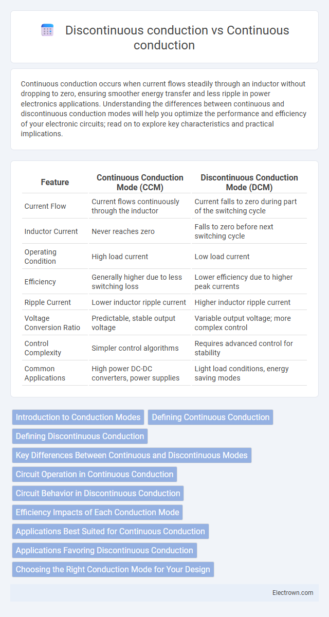
| Feature | Continuous Conduction Mode (CCM) | Discontinuous Conduction Mode (DCM) |
|---|---|---|
| Current Flow | Current flows continuously through the inductor | Current falls to zero during part of the switching cycle |
| Inductor Current | Never reaches zero | Falls to zero before next switching cycle |
| Operating Condition | High load current | Low load current |
| Efficiency | Generally higher due to less switching loss | Lower efficiency due to higher peak currents |
| Ripple Current | Lower inductor ripple current | Higher inductor ripple current |
| Voltage Conversion Ratio | Predictable, stable output voltage | Variable output voltage; more complex control |
| Control Complexity | Simpler control algorithms | Requires advanced control for stability |
| Common Applications | High power DC-DC converters, power supplies | Light load conditions, energy saving modes |
Introduction to Conduction Modes
Continuous conduction mode (CCM) occurs when current through an inductor never falls to zero during the switching cycle, ensuring a constant energy flow and reduced ripple in power converters. Discontinuous conduction mode (DCM) happens when the inductor current drops to zero for a portion of the switching period, typically improving efficiency at light loads but increasing output voltage ripple. Understanding these conduction modes is crucial for optimizing your power supply design, balancing efficiency, and electromagnetic interference in various applications.
Defining Continuous Conduction
Continuous conduction occurs when current flows uninterruptedly through an inductor during the entire switching cycle, ensuring the inductor current never drops to zero. This mode maintains a steady energy transfer, reducing ripple and improving efficiency in power converters, especially in buck and boost regulators. Understanding your converter's conduction mode helps optimize performance and prevent potential inefficiencies associated with discontinuous conduction.
Defining Discontinuous Conduction
Discontinuous conduction occurs in power electronics when the current through an inductor drops to zero during part of the switching cycle, causing intervals with no energy transfer. This mode contrasts with continuous conduction, where current remains above zero throughout the cycle, ensuring steady energy flow. Discontinuous conduction impacts converter efficiency, switching losses, and requires specific control strategies to maintain voltage regulation and system stability.
Key Differences Between Continuous and Discontinuous Modes
Continuous conduction mode (CCM) occurs when the current through an inductor never falls to zero during the switching cycle, maintaining a steady energy flow, whereas discontinuous conduction mode (DCM) features current that drops to zero, causing intermittent energy transfer. CCM generally provides smoother output voltage and higher efficiency at heavier loads, while DCM is more common at lighter loads, resulting in increased switching losses and voltage ripple. The transition between these modes is determined by load conditions, switching frequency, and inductor value, crucial for optimizing power converter performance.
Circuit Operation in Continuous Conduction
Circuit operation in continuous conduction mode (CCM) occurs when the current through the inductor never falls to zero during the entire switching cycle, ensuring a constant flow of energy. This mode enhances efficiency by reducing current ripple and minimizing electromagnetic interference, making it ideal for power supplies and converters operating at higher loads. You can achieve stable voltage regulation and improved performance by maintaining CCM in your power electronic circuits.
Circuit Behavior in Discontinuous Conduction
In discontinuous conduction mode (DCM), the current through the inductor falls to zero during part of the switching cycle, causing the circuit to exhibit non-linear behavior and increased switching losses compared to continuous conduction mode (CCM). This mode is characterized by intervals where the inductor current is zero, resulting in reduced average current and potentially higher peak currents, which affect the efficiency and thermal performance of power converters. Circuits operating in DCM require careful design considerations for control loop stability and transient response due to the changing inductor current dynamics.
Efficiency Impacts of Each Conduction Mode
Continuous conduction mode (CCM) maintains current flow throughout the entire switching cycle, resulting in lower conduction losses and improved efficiency in power converters under moderate to high load conditions. Discontinuous conduction mode (DCM), characterized by current dropping to zero before the next switching cycle, often leads to higher switching losses and reduced efficiency, especially at light loads. Understanding how your system operates in CCM versus DCM helps optimize efficiency by balancing conduction and switching losses tailored to your specific load requirements.
Applications Best Suited for Continuous Conduction
Continuous conduction mode (CCM) is best suited for applications requiring stable and efficient power delivery, such as high-power DC-DC converters, motor drives, and power supply systems in electric vehicles. CCM ensures lower current ripple and improved electromagnetic compatibility, making it ideal for sensitive electronic devices and industrial automation requiring consistent torque and smooth operation. These advantages contribute to enhanced system reliability and reduced thermal stress in continuous load environments.
Applications Favoring Discontinuous Conduction
Discontinuous conduction mode (DCM) is favored in low-power applications such as battery-operated devices and portable electronics due to its improved efficiency at light loads and reduced switching losses. Switch-mode power supplies and DC-DC converters often operate in DCM to minimize electromagnetic interference (EMI) and achieve better transient response. High-frequency transformers and inductors benefit from DCM by operating with smaller magnetic components, which reduces weight and size in compact power systems.
Choosing the Right Conduction Mode for Your Design
Choosing the right conduction mode for your design depends on load conditions and efficiency requirements, with continuous conduction mode (CCM) favored for high load currents due to reduced ripple and improved performance. Discontinuous conduction mode (DCM) suits lighter loads by minimizing switching losses and simplifying control, though it may introduce higher current stress and noise. Balancing these factors ensures optimal power conversion efficiency and thermal management in applications such as DC-DC converters and motor drives.
Continuous conduction vs Discontinuous conduction Infographic