I/Q imbalance and DC offset are critical issues in communication systems affecting signal integrity by causing distortion and degrading performance. Understanding their differences and impacts can help you optimize your system's accuracy and efficiency--continue reading to explore detailed solutions and techniques.
Table of Comparison
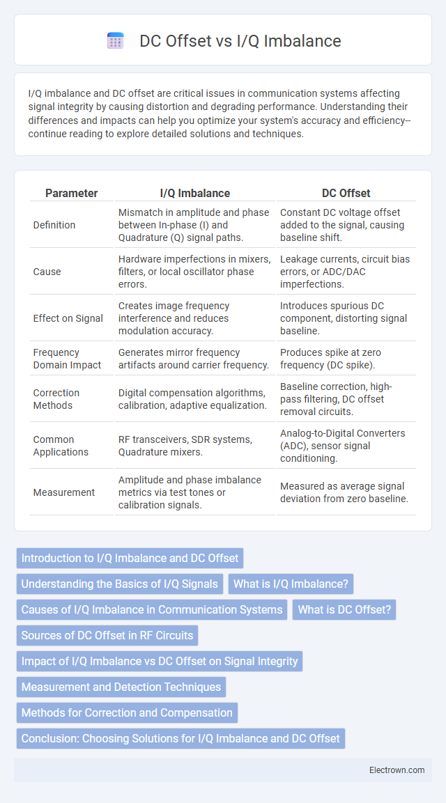
| Parameter | I/Q Imbalance | DC Offset |
|---|---|---|
| Definition | Mismatch in amplitude and phase between In-phase (I) and Quadrature (Q) signal paths. | Constant DC voltage offset added to the signal, causing baseline shift. |
| Cause | Hardware imperfections in mixers, filters, or local oscillator phase errors. | Leakage currents, circuit bias errors, or ADC/DAC imperfections. |
| Effect on Signal | Creates image frequency interference and reduces modulation accuracy. | Introduces spurious DC component, distorting signal baseline. |
| Frequency Domain Impact | Generates mirror frequency artifacts around carrier frequency. | Produces spike at zero frequency (DC spike). |
| Correction Methods | Digital compensation algorithms, calibration, adaptive equalization. | Baseline correction, high-pass filtering, DC offset removal circuits. |
| Common Applications | RF transceivers, SDR systems, Quadrature mixers. | Analog-to-Digital Converters (ADC), sensor signal conditioning. |
| Measurement | Amplitude and phase imbalance metrics via test tones or calibration signals. | Measured as average signal deviation from zero baseline. |
Introduction to I/Q Imbalance and DC Offset
I/Q imbalance arises from mismatches in amplitude and phase between the in-phase (I) and quadrature (Q) components of a signal, impacting the accuracy of complex signal demodulation in communication systems. DC offset refers to a constant voltage shift added to the baseband signal, causing distortion and degrading receiver performance by shifting the signal constellation. Understanding and compensating for these impairments is crucial in maintaining signal integrity and optimizing your wireless system's performance.
Understanding the Basics of I/Q Signals
I/Q imbalance in communication systems refers to mismatches in amplitude and phase between the in-phase (I) and quadrature (Q) components of a signal, causing distortion and degraded signal quality. DC offset, on the other hand, is a constant voltage shift in the I or Q channel that skews the signal's baseline, leading to inaccuracies in demodulation. Understanding the differences between I/Q imbalance and DC offset is essential for optimizing receiver performance in complex modulation schemes such as QAM and OFDM.
What is I/Q Imbalance?
I/Q imbalance refers to the mismatches in amplitude and phase between the in-phase (I) and quadrature (Q) components of a modulated signal, leading to signal distortion and degraded receiver performance. These discrepancies cause mirror frequency interference and reduce the effectiveness of communication systems, especially in complex modulation schemes like QAM or OFDM. Correcting I/Q imbalance is critical for maintaining signal integrity and optimizing the overall wireless communication quality.
Causes of I/Q Imbalance in Communication Systems
I/Q imbalance in communication systems primarily arises from mismatches in amplitude and phase between the in-phase (I) and quadrature (Q) signal paths caused by component imperfections like mixers, filters, and amplifiers. Variations in fabrication processes and temperature changes also contribute to I/Q imbalance by altering the gain and phase response of analog front-end components. Unlike DC offset, which stems from direct current leakage or self-mixing effects, I/Q imbalance distorts the signal constellation, leading to degraded modulation accuracy and increased error vector magnitude (EVM).
What is DC Offset?
DC offset refers to a constant voltage shift in a signal's baseline, causing the signal to deviate from zero even in the absence of input. It typically arises from imperfections in analog components, such as mixers or amplifiers, leading to distortion in both time and frequency domains. Correcting DC offset is crucial for accurate signal demodulation and minimizing errors in digital communication systems.
Sources of DC Offset in RF Circuits
DC offset in RF circuits primarily originates from imperfections in active components such as mixers, amplifiers, and ADCs, causing unwanted shifts in the signal baseline. Mismatches in the differential circuit layout and process variations further contribute to DC offset by introducing asymmetries in the analog signal path. Thermal variations and leakage currents in transistors also generate DC offset, which can significantly degrade system performance if not properly compensated.
Impact of I/Q Imbalance vs DC Offset on Signal Integrity
I/Q imbalance causes distortion in the in-phase and quadrature components, leading to image interference and degraded signal quality, which directly impacts demodulation accuracy. DC offset introduces a constant bias in the received signal, resulting in baseline shifts that can cause symbol misinterpretation and increase error rates. Your communication system's signal integrity is more severely compromised by I/Q imbalance due to its complex effect on amplitude and phase, whereas DC offset primarily affects the signal baseline.
Measurement and Detection Techniques
Measurement and detection techniques for I/Q imbalance involve analyzing the amplitude and phase differences between the in-phase (I) and quadrature (Q) components using vector signal analyzers and digital signal processing algorithms. DC offset detection relies on measuring the mean value of the signal's baseband components, typically through averaging methods or using DC blocking filters to isolate and quantify the offset voltage. Advanced methods incorporate calibration routines and adaptive algorithms to correct these impairments in real-time, enhancing overall signal integrity in communication systems.
Methods for Correction and Compensation
I/Q imbalance correction methods commonly utilize adaptive algorithms such as Least Mean Squares (LMS) or Recursive Least Squares (RLS) to dynamically estimate and compensate amplitude and phase mismatches between the in-phase (I) and quadrature (Q) signal components. DC offset compensation techniques often involve high-pass filtering or digital DC estimators that track and remove zero-frequency components introduced by hardware imperfections. Advanced systems combine joint estimation frameworks to simultaneously address both I/Q imbalance and DC offset, enhancing overall receiver performance and signal integrity.
Conclusion: Choosing Solutions for I/Q Imbalance and DC Offset
Choosing the right solution for I/Q imbalance and DC offset depends on the specific system requirements and signal conditions, with adaptive compensation algorithms often providing effective correction for dynamic impairments. Calibration techniques and hardware improvements can also minimize these issues but may increase design complexity and cost. Your decision should balance performance, implementation complexity, and system constraints to optimize overall signal quality.
I/Q Imbalance vs DC Offset Infographic