DCS capacitors offer improved capacitance density and lower parasitic effects compared to traditional MIM capacitors, which feature a straightforward metal-insulator-metal layer structure for reliable performance. Explore the differences in their construction, advantages, and applications to decide which capacitor best suits your electronic design needs by reading the full article.
Table of Comparison
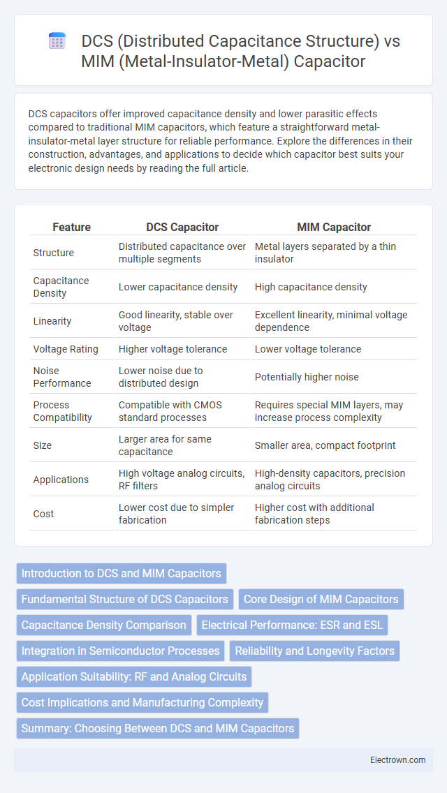
| Feature | DCS Capacitor | MIM Capacitor |
|---|---|---|
| Structure | Distributed capacitance over multiple segments | Metal layers separated by a thin insulator |
| Capacitance Density | Lower capacitance density | High capacitance density |
| Linearity | Good linearity, stable over voltage | Excellent linearity, minimal voltage dependence |
| Voltage Rating | Higher voltage tolerance | Lower voltage tolerance |
| Noise Performance | Lower noise due to distributed design | Potentially higher noise |
| Process Compatibility | Compatible with CMOS standard processes | Requires special MIM layers, may increase process complexity |
| Size | Larger area for same capacitance | Smaller area, compact footprint |
| Applications | High voltage analog circuits, RF filters | High-density capacitors, precision analog circuits |
| Cost | Lower cost due to simpler fabrication | Higher cost with additional fabrication steps |
Introduction to DCS and MIM Capacitors
DCS (Distributed Capacitance Structure) capacitors utilize a network of interconnected conductive elements to achieve capacitance through distributed electric fields, offering superior high-frequency performance and reduced parasitic effects. MIM (Metal-Insulator-Metal) capacitors consist of two metal plates separated by a thin insulating layer, providing high capacitance density and excellent linearity ideal for analog and RF applications. Your choice between DCS and MIM capacitors depends on specific circuit requirements such as frequency response, size constraints, and linearity needs.
Fundamental Structure of DCS Capacitors
The fundamental structure of Distributed Capacitance Structure (DCS) capacitors consists of multiple interleaved conductive layers separated by dielectric materials, forming a grid-like pattern that distributes capacitance over a broad area to reduce parasitic inductance and resistance. This architecture enhances frequency performance and thermal stability by minimizing localized electric field concentration compared to the compact, planar Metal-Insulator-Metal (MIM) capacitors, which rely on stacked metal plates separated by a uniform insulator. The DCS capacitor's distributed layout enables improved linearity and high Q-factor at microwave frequencies, making it ideal for RF and high-speed analog applications.
Core Design of MIM Capacitors
The core design of MIM capacitors features two metal plates separated by a thin insulating dielectric layer, enabling high capacitance density and low equivalent series resistance (ESR). This structure ensures excellent linearity, stability, and low parasitic inductance, making MIM capacitors ideal for high-frequency and precision applications. Compared to DCS capacitors, MIM capacitors provide superior performance in terms of voltage coefficient and temperature stability due to their uniform dielectric and metal electrode configurations.
Capacitance Density Comparison
DCS (Distributed Capacitance Structure) capacitors typically offer higher capacitance density compared to MIM (Metal-Insulator-Metal) capacitors due to their multi-layered layout that maximizes surface area within a limited footprint. MIM capacitors provide stable dielectric properties but generally achieve lower capacitance density because of thicker dielectric layers and simpler planar geometry. Advanced semiconductor processes enhance DCS capacitor integration, enabling more compact designs with increased capacitance per unit area than conventional MIM capacitors.
Electrical Performance: ESR and ESL
DCS capacitors exhibit lower Equivalent Series Resistance (ESR) compared to MIM capacitors due to their distributed capacitance layout, which improves current distribution and reduces resistive losses. The structural design of DCS also minimizes Equivalent Series Inductance (ESL), enhancing high-frequency performance critical for RF and microwave applications. In contrast, MIM capacitors may present higher ESR and ESL values due to their compact layered construction, impacting efficiency in high-speed circuits.
Integration in Semiconductor Processes
DCS (Distributed Capacitance Structure) capacitors offer enhanced integration compatibility with advanced semiconductor processes due to their ability to utilize existing device layers, reducing additional fabrication steps and costs. MIM (Metal-Insulator-Metal) capacitors require precise deposition of dielectric materials and metal layers, which can complicate process integration and increase manufacturing complexity. Semiconductor foundries favor DCS capacitors for high-density on-chip applications where seamless integration and minimal process disruption are critical.
Reliability and Longevity Factors
DCS (Distributed Capacitance Structure) capacitors exhibit superior reliability due to their distributed electrode design, which reduces localized electric field stress and minimizes the risk of dielectric breakdown. MIM (Metal-Insulator-Metal) capacitors, while offering high capacitance density, can suffer from thin dielectric layers that increase susceptibility to leakage currents and premature failure under prolonged voltage stress. Longevity in DCS capacitors is enhanced by lower operating temperatures and better tolerance to voltage fluctuations, whereas MIM capacitors require careful process control to maintain dielectric integrity for extended device lifespan.
Application Suitability: RF and Analog Circuits
DCS capacitors offer superior linearity and low parasitic capacitance, making them ideal for high-frequency RF circuits where signal integrity and minimal losses are critical. MIM capacitors provide higher capacitance density and excellent matching, often preferred in analog circuits requiring precise charge storage and stable capacitance under varying voltage conditions. Both types support RF and analog applications, but DCS excels in high-frequency performance while MIM suits compact, precision analog designs.
Cost Implications and Manufacturing Complexity
DCS (Distributed Capacitance Structure) capacitors typically offer lower manufacturing complexity due to simpler layering and patterning processes compared to MIM (Metal-Insulator-Metal) capacitors, which require precise deposition of high-quality dielectric materials to ensure performance. The cost implications of DCS capacitors are generally lower, benefiting from standard semiconductor fabrication techniques without the need for specialized insulating layers, while MIM capacitors incur higher costs due to additional material requirements and tighter process controls. Consequently, DCS capacitors are preferred for cost-sensitive applications where moderate capacitance density suffices, whereas MIM capacitors suit high-performance designs demanding superior capacitance linearity and stability despite increased fabrication expenses.
Summary: Choosing Between DCS and MIM Capacitors
DCS capacitors offer lower parasitic resistance and improved high-frequency performance, making them suitable for RF and power applications requiring high linearity. MIM capacitors provide higher density and better voltage handling with superior matching accuracy, ideal for integrated analog circuits and precision filtering. Selecting between DCS and MIM capacitors depends on balancing frequency response, footprint constraints, and application-specific voltage and linearity demands.
DCS (Distributed Capacitance Structure) vs MIM (Metal-Insulator-Metal) capacitor Infographic