Quarter wave transformers provide impedance matching at a specific frequency by using a transmission line length equal to a quarter wavelength, ensuring minimal reflection and maximum power transfer. Exploring the differences between Quarter Wave Transformers and Tapered Lines can help you optimize your RF design; read on to learn which method suits your application best.
Table of Comparison
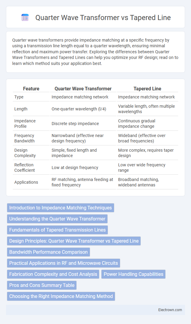
| Feature | Quarter Wave Transformer | Tapered Line |
|---|---|---|
| Type | Impedance matching network | Impedance matching network |
| Length | One-quarter wavelength (l/4) | Variable length, often multiple wavelengths |
| Impedance Profile | Discrete step impedance | Continuous gradual impedance change |
| Frequency Bandwidth | Narrowband (effective near design frequency) | Wideband (effective over broad frequencies) |
| Design Complexity | Simple, fixed length and impedance | More complex, requires taper design |
| Reflection Coefficient | Low at design frequency | Low over wide frequency range |
| Applications | RF matching, antenna feeding at fixed frequency | Broadband matching, wideband antennas |
Introduction to Impedance Matching Techniques
Quarter Wave Transformers and Tapered Lines are fundamental impedance matching techniques used to optimize power transfer between transmission lines of different impedances. Quarter Wave Transformers use a single section of transmission line with a specific length and characteristic impedance to match two lines, ideal for narrowband applications. Tapered Lines gradually change the impedance over a length, providing broadband matching suitable for wide frequency ranges and minimizing signal reflection.
Understanding the Quarter Wave Transformer
Quarter Wave Transformers are used in impedance matching by utilizing a specific length of transmission line equal to one-quarter of the signal wavelength, transforming load impedance to match the source impedance efficiently. This method is ideal for narrowband applications where precise frequency tuning is possible, unlike tapered lines that provide broadband impedance matching through gradual impedance variation. You can achieve minimal reflection and maximized power transfer in RF circuits by choosing a Quarter Wave Transformer when operating at a specific frequency.
Fundamentals of Tapered Transmission Lines
Tapered transmission lines gradually vary their characteristic impedance along their length to minimize signal reflection and improve impedance matching in RF circuits. Unlike quarter wave transformers, which rely on a specific electrical length (l/4) to achieve impedance transformation, tapered lines use a continuous impedance profile to provide broadband performance and reduced insertion loss. This gradual impedance transition makes tapered lines highly effective in wideband applications and complex impedance matching scenarios.
Design Principles: Quarter Wave Transformer vs Tapered Line
The Quarter Wave Transformer relies on a section of transmission line with a length equal to one-quarter of the wavelength to provide impedance matching through a specific characteristic impedance calculated from the load and source impedances. In contrast, the Tapered Line utilizes a gradual, continuous change in impedance along the length of the transmission line to minimize reflections and achieve broadband impedance matching. The design principle of the Quarter Wave Transformer is frequency-specific due to its fixed length, while the Tapered Line supports wideband performance by smoothly transitioning impedances.
Bandwidth Performance Comparison
Quarter wave transformers provide narrow bandwidth matching due to their fixed electrical length at a single frequency, limiting their effectiveness across wide frequency ranges. Tapered lines, such as exponential or Klopfenstein tapers, offer significantly improved bandwidth performance by gradually transitioning impedance, minimizing reflections over a broad spectrum. You should choose tapered line matching when wideband operation and low return loss are critical to your RF or microwave system design.
Practical Applications in RF and Microwave Circuits
Quarter Wave Transformers are widely used in RF and microwave circuits for impedance matching due to their simplicity and effectiveness at a specific frequency, making them ideal for narrowband applications such as antenna feeding networks and filters. Tapered Lines provide a smooth impedance transition over a wide frequency range, offering superior performance in broadband matching scenarios like broadband amplifiers and wideband antennas. Engineers select Quarter Wave Transformers for fixed-frequency designs and Tapered Lines when broadband impedance matching and reduced reflection are critical.
Fabrication Complexity and Cost Analysis
Quarter wave transformers typically offer simpler fabrication due to their uniform transmission line sections, resulting in lower manufacturing costs. Tapered lines require precise gradual impedance variation, increasing fabrication complexity and material use, which elevates production expenses. Your choice should consider budget constraints and the needed performance precision, as the quarter wave transformer is cost-effective while tapered lines provide smoother impedance matching at a higher cost.
Power Handling Capabilities
Quarter Wave Transformers offer limited power handling capabilities due to their narrowband nature and abrupt impedance transitions, which can cause increased reflections and localized heating. Tapered Lines provide superior power handling by gradually transitioning impedance over a broad bandwidth, reducing voltage standing wave ratio (VSWR) and minimizing losses. Your choice should consider the operational power levels and bandwidth requirements to optimize performance and reliability.
Pros and Cons Summary Table
Quarter Wave Transformers provide simple impedance matching with a fixed frequency design, ideal for narrow bandwidth applications. Tapered Lines offer broadband impedance matching by gradually varying the impedance, enhancing performance over wide frequency ranges but with increased design complexity. The Quarter Wave Transformer is compact and easy to fabricate, while the Tapered Line requires more space and precise fabrication to achieve optimal broadband matching.
Choosing the Right Impedance Matching Method
Selecting the right impedance matching method depends on your system's frequency range and bandwidth requirements. Quarter Wave Transformers provide excellent performance in narrowband applications by transforming impedances at a specific frequency using a precise quarter-wavelength transmission line. Tapered Lines, on the other hand, offer broad bandwidth matching by gradually transitioning impedance, making them ideal for wideband or multi-frequency systems.
Quarter Wave Transformer vs Tapered Line Infographic