Impedance matching ensures the load impedance equals the source impedance to maximize power transfer efficiency and minimize signal reflection in electrical circuits. Understanding the subtle differences between impedance matching and maximum power transfer can enhance Your system's performance--read on to explore these critical concepts in detail.
Table of Comparison
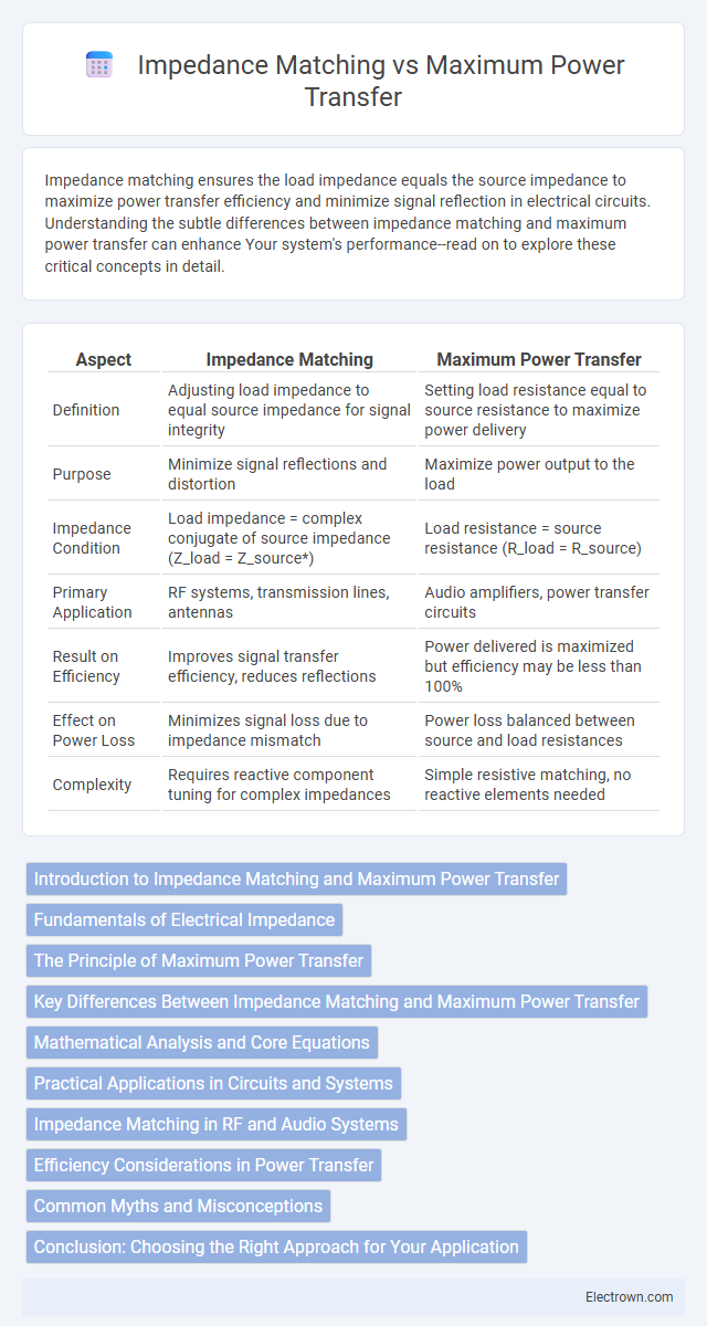
| Aspect | Impedance Matching | Maximum Power Transfer |
|---|---|---|
| Definition | Adjusting load impedance to equal source impedance for signal integrity | Setting load resistance equal to source resistance to maximize power delivery |
| Purpose | Minimize signal reflections and distortion | Maximize power output to the load |
| Impedance Condition | Load impedance = complex conjugate of source impedance (Z_load = Z_source*) | Load resistance = source resistance (R_load = R_source) |
| Primary Application | RF systems, transmission lines, antennas | Audio amplifiers, power transfer circuits |
| Result on Efficiency | Improves signal transfer efficiency, reduces reflections | Power delivered is maximized but efficiency may be less than 100% |
| Effect on Power Loss | Minimizes signal loss due to impedance mismatch | Power loss balanced between source and load resistances |
| Complexity | Requires reactive component tuning for complex impedances | Simple resistive matching, no reactive elements needed |
Introduction to Impedance Matching and Maximum Power Transfer
Impedance matching involves adjusting the load impedance to equal the source impedance to maximize signal transfer and minimize reflections in electrical circuits. Maximum power transfer occurs when the load impedance is the complex conjugate of the source impedance, ensuring maximum energy delivery from source to load. Understanding these principles is crucial in RF systems, audio engineering, and power electronics to optimize system efficiency and performance.
Fundamentals of Electrical Impedance
Electrical impedance represents the total opposition a circuit offers to alternating current, combining resistance, inductive reactance, and capacitive reactance. Impedance matching involves adjusting load impedance to equal the source impedance, minimizing reflections and maximizing signal transfer efficiency. Maximum power transfer occurs when the load impedance is the complex conjugate of the source impedance, ensuring peak power delivery to the load.
The Principle of Maximum Power Transfer
The Principle of Maximum Power Transfer states that maximum power is delivered from a source to a load when the load impedance matches the complex conjugate of the source impedance, minimizing reflections and energy loss. Impedance matching is essential in communication systems, audio electronics, and RF circuits to ensure efficient signal transmission and reduce distortion. Your system's performance significantly improves by optimizing load impedance according to this principle, resulting in enhanced power efficiency and signal integrity.
Key Differences Between Impedance Matching and Maximum Power Transfer
Impedance matching ensures the load impedance equals the source impedance to minimize signal reflection and optimize energy delivery in RF and communication systems. Maximum power transfer occurs when the load impedance is the complex conjugate of the source impedance, allowing the highest possible power flow but often sacrificing efficiency. While impedance matching prioritizes signal integrity and minimal loss, maximum power transfer targets maximum output power regardless of potential energy dissipation.
Mathematical Analysis and Core Equations
Impedance matching ensures the load impedance equals the source impedance conjugate, minimizing signal reflection and maximizing power delivery, expressed as \( Z_L = Z_S^* \). Maximum power transfer theorem states that maximum power is delivered to the load when \( R_L = R_S \) and the load's reactance cancels the source's reactance, derived from the power equation \( P = \frac{V^2}{4R_S} \). Your system performance can be optimized by using these core equations to balance efficiency and power: \( Z_L = R_S - jX_S \) and \( P_{max} = \frac{V^2}{4R_S} \).
Practical Applications in Circuits and Systems
Impedance matching ensures optimal signal transmission and minimal reflections in RF circuits, audio systems, and communication devices, enhancing overall system efficiency. Maximum power transfer is crucial in power delivery applications such as battery chargers and wireless power systems, where matching load impedance to the source maximizes energy transfer. Understanding these principles helps you design circuits that balance efficiency, signal integrity, and power delivery for various practical applications.
Impedance Matching in RF and Audio Systems
Impedance matching in RF and audio systems ensures maximum power transfer by aligning the source and load impedances, minimizing signal reflection and losses. In RF systems, precise impedance matching is critical to maintain signal integrity and optimize antenna performance, often achieved using matching networks or tuners. Your audio equipment benefits from impedance matching by delivering clearer sound, preventing distortion, and protecting components from potential damage.
Efficiency Considerations in Power Transfer
Impedance matching optimizes the transfer of power by ensuring the load impedance equals the source impedance, maximizing power output to the load but not always maximizing efficiency. Maximum power transfer occurs when these impedances are equal, but often leads to power loss in the source, reducing overall efficiency. For Your system, balancing impedance matching with efficiency considerations often involves compromising maximum power transfer to minimize wasted energy and improve performance.
Common Myths and Misconceptions
Impedance matching is often misunderstood as always necessary for maximum power transfer, but this only holds true in purely resistive loads and specific conditions. Many believe that matching impedances guarantees the highest efficiency, yet it can actually result in significant power loss in many practical scenarios, such as in audio or RF systems where reflectance is critical. Understanding these distinctions clarifies that maximum power transfer aims to maximize delivered power, while impedance matching optimizes signal integrity and reduces reflections, which may not always align with your system goals.
Conclusion: Choosing the Right Approach for Your Application
Impedance matching ensures signal integrity and minimal reflection in high-frequency systems, while maximum power transfer prioritizes delivering optimal power from a source to a load. Your choice depends on whether your application demands signal fidelity or efficient power delivery, with impedance matching favored in communication systems and maximum power transfer critical in power amplifiers. Understanding the trade-offs between these approaches is essential for optimizing performance and achieving design goals.
Impedance Matching vs Maximum Power Transfer Infographic