Source-coupled and emitter-coupled configurations both serve as differential amplifier inputs but differ in transistor type and voltage levels, with source-coupled using MOSFETs and emitter-coupled relying on BJTs, affecting noise performance and speed. Learn more about how each impacts your circuit design and application in the rest of this article.
Table of Comparison
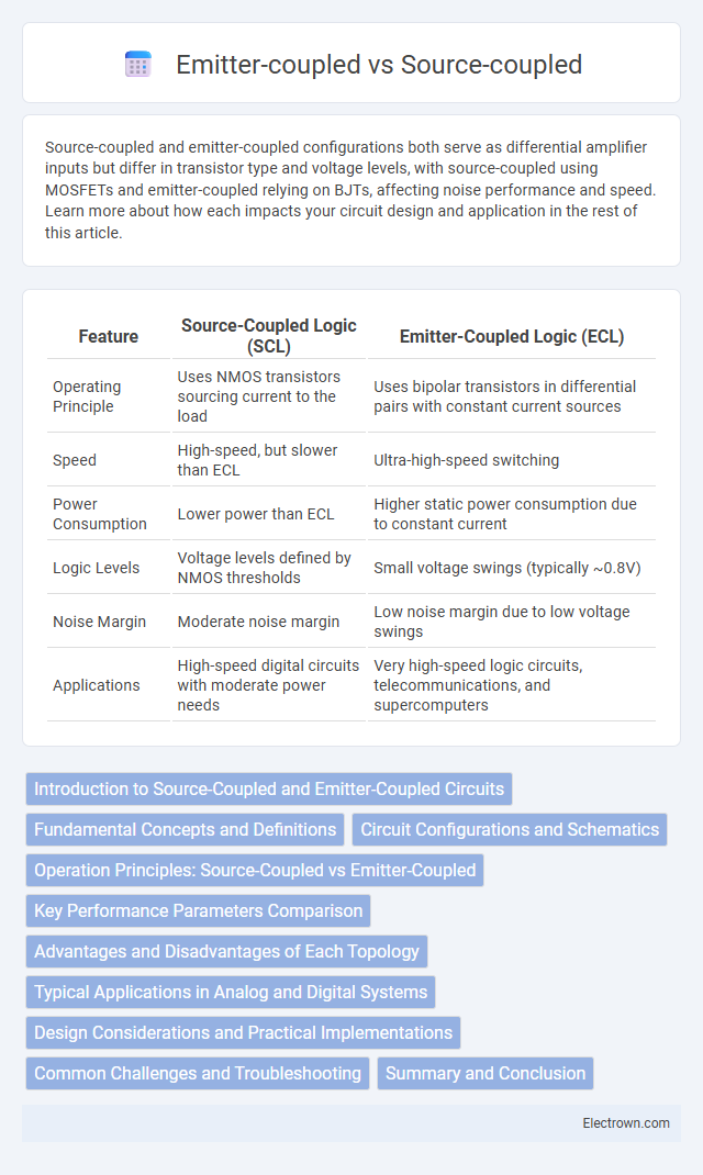
| Feature | Source-Coupled Logic (SCL) | Emitter-Coupled Logic (ECL) |
|---|---|---|
| Operating Principle | Uses NMOS transistors sourcing current to the load | Uses bipolar transistors in differential pairs with constant current sources |
| Speed | High-speed, but slower than ECL | Ultra-high-speed switching |
| Power Consumption | Lower power than ECL | Higher static power consumption due to constant current |
| Logic Levels | Voltage levels defined by NMOS thresholds | Small voltage swings (typically ~0.8V) |
| Noise Margin | Moderate noise margin | Low noise margin due to low voltage swings |
| Applications | High-speed digital circuits with moderate power needs | Very high-speed logic circuits, telecommunications, and supercomputers |
Introduction to Source-Coupled and Emitter-Coupled Circuits
Source-coupled and emitter-coupled circuits are fundamental building blocks in analog integrated circuit design, with source-coupled circuits primarily used in MOSFET technologies and emitter-coupled circuits in bipolar junction transistors (BJTs). Both topologies function as differential pairs but differ in their transistor operation, noise performance, and speed characteristics, where source-coupled circuits offer lower power consumption and emitter-coupled circuits provide higher gain and faster switching. Understanding these distinctions can help you optimize your circuit design for specific application requirements such as bandwidth, power efficiency, and linearity.
Fundamental Concepts and Definitions
Source-coupled logic (SCL) and emitter-coupled logic (ECL) are high-speed digital circuits primarily distinguished by their transistor configurations; SCL uses MOSFETs with sources connected to a current source, while ECL employs BJTs with emitters connected to a constant current source. Both logic families operate by steering current through differential pairs, enabling rapid switching and low voltage swings that minimize propagation delay. Understanding your circuit requirements helps determine whether SCL's compatibility with CMOS technology or ECL's superior speed performance is more suitable for your high-frequency digital design applications.
Circuit Configurations and Schematics
Source-coupled circuits use MOSFETs with sources connected together to form a differential pair, optimizing input impedance and minimizing offset voltage, as seen in typical CMOS differential amplifier schematics. Emitter-coupled configurations employ BJTs with emitters joined via a common resistor or current source, offering high transconductance and gain, frequently represented in classic bipolar differential pair circuits. Both circuit configurations feature current mirrors and tail current sources but diverge in device type and voltage headroom requirements, impacting schematic design and performance trade-offs.
Operation Principles: Source-Coupled vs Emitter-Coupled
Source-coupled circuits operate by using MOSFET transistors where the current source is connected to the sources of transistors, enabling high input impedance and faster switching speeds suitable for CMOS technology. Emitter-coupled circuits utilize bipolar junction transistors with the current source connected to the emitters, providing higher transconductance and improved linearity for analog applications. Understanding these operation principles helps you select the appropriate coupling method based on your design requirements for speed, impedance, and signal fidelity.
Key Performance Parameters Comparison
Source-coupled logic (SCL) and emitter-coupled logic (ECL) differ significantly in speed, power consumption, and noise margin. SCL typically offers lower power dissipation due to its MOS transistor-based design, while ECL provides superior switching speed and higher noise immunity attributed to its bipolar junction transistor architecture. The voltage swing in ECL is generally smaller, enabling faster transitions, whereas SCL yields better voltage compatibility with CMOS levels, influencing integration decisions based on application requirements.
Advantages and Disadvantages of Each Topology
Source-coupled logic (SCL) offers lower power consumption and better noise immunity due to its current-steering nature, making it suitable for high-speed, low-power applications, but it tends to have slower transition times and increased circuit complexity compared to emitter-coupled logic (ECL). Emitter-coupled logic excels in ultra-high-speed switching and better timing characteristics due to its differential transistor pair topology but consumes more power and generates greater heat, which can limit its use in power-sensitive environments. Choosing between SCL and ECL depends on the trade-off between speed, power efficiency, and circuit complexity tailored to specific application requirements.
Typical Applications in Analog and Digital Systems
Source-coupled logic (SCL) is predominantly used in high-speed analog circuits and low-power digital systems due to its low voltage swing and high noise immunity, making it ideal for applications like differential amplifiers and data converters. Emitter-coupled logic (ECL) finds widespread use in ultra-high-speed digital circuits such as clock distribution networks and high-frequency communication systems because of its fast switching speeds and minimal propagation delay. Both SCL and ECL are crucial in mixed-signal designs where optimizing speed, power efficiency, and noise margins determines overall system performance.
Design Considerations and Practical Implementations
Source-coupled and emitter-coupled circuits differ primarily in their biasing and thermal stability, influencing design considerations such as noise performance and speed. Source-coupled circuits, often used in MOSFET technology, offer lower input voltage requirements and better integration scalability, benefiting RF and high-frequency applications. Emitter-coupled designs, typical in bipolar transistor circuits, provide superior gain and linearity, making them preferred for analog signal processing where precise current control and thermal compensation are critical.
Common Challenges and Troubleshooting
Source-coupled and emitter-coupled circuits both face challenges like device mismatch, thermal drift, and limited gain bandwidth, which can impact signal integrity and performance. Troubleshooting often involves careful bias current adjustment, temperature stabilization techniques, and precise layout to minimize parasitic effects and mismatch. Understanding your circuit's specific requirements and employing proper compensation methods helps optimize operational efficiency and reduce noise susceptibility.
Summary and Conclusion
Source-coupled logic (SCL) offers lower power consumption and improved noise immunity by using a common source node for transistors, making it ideal for low-voltage applications. Emitter-coupled logic (ECL) provides superior speed and high-frequency performance through differential transistor pairs with constant current biasing. Selecting between Source-coupled and Emitter-coupled designs depends on prioritizing power efficiency versus switching speed in high-speed digital circuits.
Source-coupled vs Emitter-coupled Infographic