N-Channel JFETs offer higher electron mobility, resulting in faster switching speeds and better conductivity compared to P-Channel JFETs, which have lower hole mobility but provide simpler control in certain circuits. Explore the detailed comparison to understand how Your choice between these two types can impact circuit performance and efficiency.
Table of Comparison
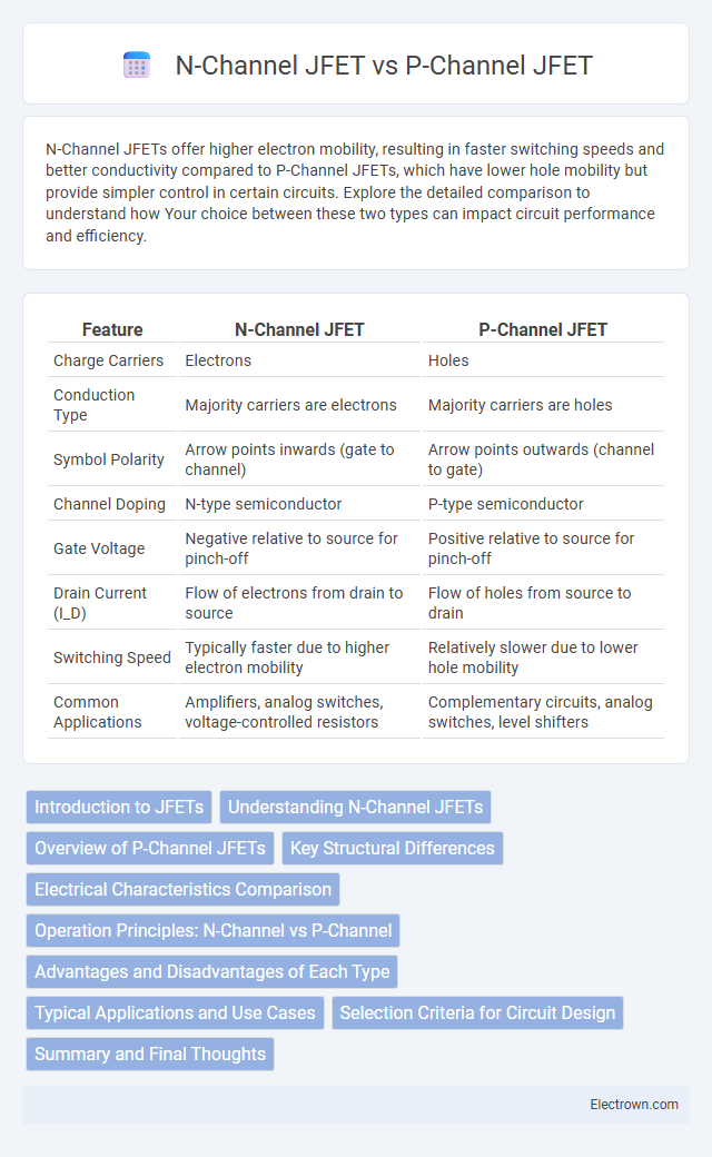
| Feature | N-Channel JFET | P-Channel JFET |
|---|---|---|
| Charge Carriers | Electrons | Holes |
| Conduction Type | Majority carriers are electrons | Majority carriers are holes |
| Symbol Polarity | Arrow points inwards (gate to channel) | Arrow points outwards (channel to gate) |
| Channel Doping | N-type semiconductor | P-type semiconductor |
| Gate Voltage | Negative relative to source for pinch-off | Positive relative to source for pinch-off |
| Drain Current (I_D) | Flow of electrons from drain to source | Flow of holes from source to drain |
| Switching Speed | Typically faster due to higher electron mobility | Relatively slower due to lower hole mobility |
| Common Applications | Amplifiers, analog switches, voltage-controlled resistors | Complementary circuits, analog switches, level shifters |
Introduction to JFETs
N-Channel JFETs and P-Channel JFETs are types of Junction Field Effect Transistors that control current flow through voltage applied to their gate terminal. N-Channel JFETs utilize electrons as majority carriers, providing higher electron mobility and typically lower ON resistance compared to P-Channel JFETs, which use holes as majority carriers. These devices are essential in analog circuit designs for switching and amplification due to their high input impedance and low noise characteristics.
Understanding N-Channel JFETs
N-Channel JFETs utilize electrons as the majority charge carriers, offering higher electron mobility and better conductivity compared to P-Channel JFETs, which use holes. The gate voltage in N-Channel JFETs controls the current flow by creating a depletion region that restricts electron movement, enabling efficient switching and amplification in high-frequency applications. Their lower noise and faster switching speeds make N-Channel JFETs preferred in analog circuits, RF amplifiers, and voltage-controlled resistors.
Overview of P-Channel JFETs
P-Channel JFETs are semiconductor devices where the channel is composed of p-type material, allowing current flow through holes as majority carriers, which differentiates them from N-Channel JFETs that use electrons. They operate by reverse-biasing the gate-source junction, controlling current via depletion of the p-channel, and are typically used in high-voltage, low-noise analog switching applications. Compared to N-Channel JFETs, P-Channel devices usually exhibit lower electron mobility and slower switching speeds but offer complementary performance in circuits requiring matched pairs or specific polarity configurations.
Key Structural Differences
N-Channel JFETs feature an n-type semiconductor channel with p-type gates on both sides, allowing electrons as the majority carriers, which results in higher electron mobility and faster operation. P-Channel JFETs, conversely, have a p-type channel with n-type gates, where holes serve as the majority carriers, typically causing lower conductivity and slower switching speeds. The polarity of the gate-channel junctions and carrier types directly influence the device's threshold voltage and electrical characteristics.
Electrical Characteristics Comparison
N-Channel JFETs typically exhibit higher electron mobility, resulting in faster switching speeds and lower on-resistance compared to P-Channel JFETs, which rely on hole mobility. The electrical characteristics of N-Channel devices include higher current capacity and better conductivity, making them suitable for high-frequency applications. Your choice between N-Channel and P-Channel JFETs should consider these differences in voltage thresholds, transconductance, and inherent conductivity to optimize circuit performance.
Operation Principles: N-Channel vs P-Channel
N-Channel JFETs operate by allowing electrons to flow from source to drain, controlled by the voltage applied to the gate, which creates a depletion region narrowing the conductive channel. P-Channel JFETs function similarly but use holes as the charge carriers, with the gate voltage reverse-biasing the p-type channel to regulate current. Understanding these operation principles helps you choose the right JFET type for your circuit's voltage and polarity requirements.
Advantages and Disadvantages of Each Type
N-Channel JFETs offer higher electron mobility, resulting in faster switching speeds and better conductivity compared to P-Channel JFETs, making them ideal for high-frequency applications. P-Channel JFETs, while generally slower due to hole mobility, provide easier integration in complementary circuits and can simplify the design of certain analog switches. Your choice depends on performance requirements and circuit configuration, as N-Channel devices excel in speed and efficiency, whereas P-Channel devices offer design flexibility and simplified biasing.
Typical Applications and Use Cases
N-Channel JFETs are commonly used in low-noise amplifiers, analog switches, and signal buffering due to their higher electron mobility and faster switching speeds. P-Channel JFETs find applications in complementary push-pull amplifier stages and load switches where positive voltage control is required. Your choice depends on the circuit design, with N-Channel devices preferred for high-speed and low-noise performance, while P-Channel JFETs are utilized for simpler control and positive voltage environments.
Selection Criteria for Circuit Design
Selection of N-Channel or P-Channel JFET in circuit design depends on voltage and current requirements, with N-Channel JFETs typically offering higher electron mobility and faster switching speeds. N-Channel devices are preferred for low-noise amplification and high-frequency applications due to their lower on-resistance and greater efficiency. P-Channel JFETs are suitable for complementary or symmetrical circuit configurations, often chosen for ease of integration with P-type semiconductor substrates and specific polarity requirements.
Summary and Final Thoughts
N-Channel JFETs offer higher electron mobility, resulting in faster switching speeds and lower on-resistance compared to P-Channel JFETs, which use holes as charge carriers. P-Channel JFETs typically have higher noise levels and slower response but are essential in complementary circuits for balanced voltage control. Selecting between N-Channel and P-Channel JFETs depends on application-specific requirements such as speed, power efficiency, and device compatibility.
N-Channel JFET vs P-Channel JFET Infographic