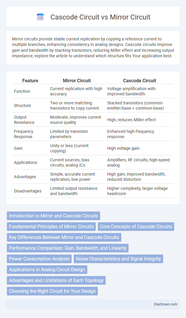
Mirror circuits provide stable current replication by copying a reference current to multiple branches, enhancing consistency in analog designs. Cascode circuits improve gain and bandwidth by stacking transistors, reducing Miller effect and increasing output impedance; explore the article to understand which structure fits Your application best.
Table of Comparison
| Feature | Mirror Circuit | Cascode Circuit |
|---|---|---|
| Function | Current replication with high accuracy | Voltage amplification with improved bandwidth |
| Structure | Two or more matching transistors to copy current | Stacked transistors (common-emitter/base + common-base) |
| Output Resistance | Moderate, improves current source quality | High, reduces Miller effect |
| Frequency Response | Limited by transistor parameters | Enhanced high-frequency response |
| Gain | Unity or less (current copying) | High voltage gain |
| Applications | Current sources, bias circuits, analog ICs | Amplifiers, RF circuits, high-speed analog |
| Advantages | Simple, accurate current replication, low power | High gain, improved bandwidth, reduced distortion |
| Disadvantages | Limited output resistance and bandwidth | Higher complexity, larger voltage headroom |
Introduction to Mirror and Cascode Circuits
Mirror circuits are designed to replicate current accurately using a matched transistor pair, enabling precise biasing and current copying in analog designs. Cascode circuits combine a common-emitter and a common-base stage to enhance gain, bandwidth, and output impedance while reducing Miller effect distortion. Your selection between mirror and cascode configurations depends on the specific needs for current replication accuracy versus frequency response and gain performance in your circuit design.
Fundamental Principles of Mirror Circuits
Mirror circuits operate based on the principle of current mirroring, where a reference current is precisely replicated to provide a stable output current regardless of load variations. This fundamental concept relies on matched transistor pairs to maintain consistent current ratios, making it essential for analog integrated circuits requiring biasing and active load functions. Your designs benefit from the simplicity and accuracy of mirror circuits in establishing reliable current sources.
Core Concepts of Cascode Circuits
Cascode circuits combine a common-emitter (or common-source) stage with a common-base (or common-gate) stage to enhance gain and bandwidth while reducing parasitic capacitances. This configuration improves output impedance and minimizes Miller effect, leading to better frequency response compared to mirror circuits. Understanding these core concepts helps you design high-performance amplifiers with improved linearity and stability.
Key Differences Between Mirror and Cascode Circuits
Mirror circuits primarily function as current mirrors to replicate current accurately, while cascode circuits enhance gain and bandwidth by stacking transistors to reduce parasitic capacitance. Key differences include their application: current mirrors are used for biasing and current replication, whereas cascode circuits improve output impedance and frequency response. Your choice depends on whether precise current replication or improved signal amplification is the priority in your design.
Performance Comparison: Gain, Bandwidth, and Linearity
The cascode circuit offers higher gain and greater bandwidth compared to the mirror circuit due to its reduced Miller effect and improved output impedance. Mirror circuits provide excellent current copying accuracy but typically exhibit lower bandwidth and gain than cascode configurations. In terms of linearity, cascode circuits generally outperform mirror circuits by minimizing voltage variations at the input transistor, thus enhancing signal integrity in high-frequency applications.
Power Consumption Analysis
Mirror circuits typically consume less power due to their simpler structure, relying mainly on current replication without additional voltage gain stages. Cascode circuits, while offering improved frequency response and gain, generally exhibit higher power consumption because of their stacked transistor configuration that increases voltage headroom requirements. Power efficiency in mirror circuits makes them suitable for low-power analog designs, whereas cascode circuits are preferred in applications demanding high gain and bandwidth despite the increased power draw.
Noise Characteristics and Signal Integrity
Mirror circuits exhibit higher noise levels due to their reliance on current mirror configurations, which introduce mismatch and thermal noise impacting signal integrity. Cascode circuits enhance noise performance by providing high output impedance and improved gain, reducing the Miller effect and minimizing parasitic capacitance effects. This leads to superior signal integrity and lower overall noise, making cascode designs preferred for high-frequency and low-noise applications.
Applications in Analog Circuit Design
Mirror circuits excel in biasing and current replication within analog integrated circuits, crucial for stable operation in amplifiers and operational amplifiers. Cascode circuits enhance frequency response and gain by stacking transistors, reducing Miller effect and improving output impedance, making them ideal for radio-frequency amplifiers and high-speed analog applications. Both circuits are essential in precision analog design, with mirror circuits providing accurate current sources and cascode configurations enabling high bandwidth and gain stages.
Advantages and Limitations of Each Topology
Mirror circuits offer precise current replication and are widely used for biasing due to their simplicity and low power consumption but suffer from limited output impedance and bandwidth. Cascode circuits provide high gain, increased output impedance, and improved frequency response, making them ideal for high-frequency applications, though they require higher voltage headroom and increased design complexity. Choosing between these topologies depends on the specific trade-offs between precision, speed, power, and design constraints in analog circuit applications.
Choosing the Right Circuit for Your Design
Choosing between a mirror circuit and a cascode circuit depends on the specific requirements of your design, such as gain, bandwidth, and output resistance. Mirror circuits excel in current replication with high accuracy and simplicity, making them ideal for biasing and current sources in analog ICs. Cascode circuits provide higher gain and improved frequency response by reducing Miller effect, suitable for high-frequency applications and low-noise amplifiers.
Mirror circuit vs cascode circuit Infographic